
HP MSR2000/3000/4000 Router Series MPLS Configuration Guide


214
127.255.255.255/32 Direct 0 0 127.0.0.1 InLoop0
192.168.10.0/24 O_ASE 150 1 30.1.1.1 Eth1/1.2
224.0.0.0/4 Direct 0 0 0.0.0.0 NULL0
224.0.0.0/24 Direct 0 0 0.0.0.0 NULL0
255.255.255.255/32 Direct 0 0 127.0.0.1 InLoop0
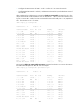
Now, the routing information for the two VPNs has been redistributed into the routing tables on PE 1.
Configuring BGP AS number substitution
Network requirements
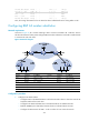
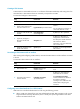
As shown in Figure 59, CE 1 and CE 2 belong to VPN 1 and are connected to PE 1 and PE 2. The two
CEs have the same AS number, 600. Configure BGP AS number substitution on the PEs to enable the CEs
to communicate with each other.
Figure 59 Network diagram
Device Interface IP address Device Interface IP address
CE 1 Eth1/1 10.1.1.1/24
P
Loop0
2.2.2.9/32
Eth1/2 100.1.1.1/24
Eth1/1
20.1.1.2/24
PE 1 Loop0 1.1.1.9/32 Eth1/2 30.1.1.1/24
Eth1/1 10.1.1.2/24
PE 2
Loop0
3.3.3.9/32
Eth1/2 20.1.1.1/24
Eth1/1
10.2.1.2/24
CE 2 Eth1/1 10.2.1.1/24 Eth1/2 30.1.1.2/24
Eth1/2 200.1.1.1/24
Configuration procedure
1. Configure basic MPLS L3VPN:
{ Configure OSPF on the MPLS backbone to allow the PEs and P device to learn the routes of the
loopback interfaces from each other.
{ Configure basic MPLS and MPLS LDP on the MPLS backbone to establish LDP LSPs.
{ Establish MP-IBGP peer relationship between the PEs to advertise VPN IPv4 routes.
{ Configure the VPN instance of VPN 1 on PE 2 to allow CE 2 to access the network.