
HP MSR2000/3000/4000 Router Series MPLS Configuration Guide


244
[P-POS5/1] mpls enable
[P-POS5/1] mpls ldp enable
[P-POS5/1] quit
# Configure PE 2.
[PE2] mpls lsr-id 3.3.3.9
[PE2] mpls ldp
[PE2-ldp] quit
[PE2] interface pos 5/0
[PE2-POS5/0] mpls enable
[PE2-POS5/0] mpls ldp enable
[PE2-POS5/0] quit
After the configurations, LDP sessions are established between PE 1, P, and PE 2. Execute the
display mpls ldp peer command. The output shows that the session status is Operational. Execute
the display mpls ldp lsp command. The output shows the LSPs established by LDP. Take PE 1 as an
example:
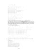
[PE1] display mpls ldp peer
Total number of peers: 1
Peer LDP ID State LAM Role GR MD5 KA Sent/Rcvd
2.2.2.9:0 Operational DU Passive Off Off 5/5
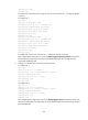
[PE1] display mpls ldp lsp
Status codes: * - stale, L - liberal
Statistics:
FECs: 3 Ingress LSPs: 2 Transit LSPs: 2 Egress LSPs: 1
FEC In/Out Label Nexthop OutInterface
1.1.1.9/32 3/-
-/1151(L)
2.2.2.9/32 -/3 172.1.1.2 POS5/0
1151/3 172.1.1.2 POS5/0
3.3.3.9/32 -/1150 172.1.1.2 POS5/0
1150/1150 172.1.1.2 POS5/0
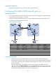
3. Configure IPv6 VPN instances on the PEs to allow CE access:
# Configure PE 1.
[PE1] ip vpn-instance vpn1
[PE1-vpn-instance-vpn1] route-distinguisher 100:1
[PE1-vpn-instance-vpn1] vpn-target 111:1
[PE1-vpn-instance-vpn1] quit
[PE1] ip vpn-instance vpn2
[PE1-vpn-instance-vpn2] route-distinguisher 100:2
[PE1-vpn-instance-vpn2] vpn-target 222:2
[PE1-vpn-instance-vpn2] quit
[PE1] interface ethernet 1/1
[PE1-Ethernet1/1] ip binding vpn-instance vpn1
[PE1-Ethernet1/1] ipv6 address 2001:1::2 96
[PE1-Ethernet1/1] quit
[PE1] interface ethernet 1/2
[PE1-Ethernet1/2] ip binding vpn-instance vpn2
[PE1-Ethernet1/2] ipv6 address 2001:2::2 96