
HP MSR2000/3000/4000 Router Series MPLS Configuration Guide


249
Configuration procedure
1. Configure an IGP on the MPLS backbone to achieve IP connectivity among the PEs and the P
router:
This example uses OSPF. (Details not shown.)
After the configurations, OSPF adjacencies are established between PE 1, P, and PE 2. Execute the
display ospf peer command. The output shows that the adjacency status is Full. Execute the display
ip routing-table command. The output shows that the PEs have learned the routes to the loopback
interfaces of each other.
2. Configure basic MPLS on the PEs:
# Configure PE 1.
<PE1> system-view
[PE1] mpls lsr-id 1.1.1.9
# Configure PE 2.
<PE2> system-view
[PE2] mpls lsr-id 2.2.2.9
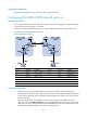
3. Configure VPN instances on the PEs to allow CE access, and apply tunnel policies to the VPN
instances to use a GRE tunnel for VPN packet forwarding:
# Configure PE 1.
[PE1] tunnel-policy gre1
[PE1-tunnel-policy-gre1] tunnel select-seq gre load-balance-number 1
[PE1-tunnel-policy-gre1] quit
[PE1] ip vpn-instance vpn1
[PE1-vpn-instance-vpn1] route-distinguisher 100:1
[PE1-vpn-instance-vpn1] vpn-target 100:1 both
[PE1-vpn-instance-vpn1] tnl-policy gre1
[PE1-vpn-instance-vpn1] quit
[PE1] interface ethernet 1/1
[PE1-Ethernet1/1] ip binding vpn-instance vpn1
[PE1-Ethernet1/1] ipv6 address 2001:1::2 96
[PE1-Ethernet1/1] quit
# Configure PE 2.
[PE2] tunnel-policy gre1
[PE2-tunnel-policy-gre1] tunnel select-seq gre load-balance-number 1
[PE2-tunnel-policy-gre1] quit
[PE2] ip vpn-instance vpn1
[PE2-vpn-instance-vpn1] route-distinguisher 100:2
[PE2-vpn-instance-vpn1] vpn-target 100:1 both
[PE2-vpn-instance-vpn1] tnl-policy gre1
[PE2-vpn-instance-vpn1] quit
[PE2] interface ethernet 1/1
[PE2-Ethernet1/1] ip binding vpn-instance vpn1
[PE2-Ethernet1/1] ipv6 address 2001:2::2 96
[PE2-Ethernet1/1] quit
# Configure CE 1.
<CE1> system-view
[CE1] interface ethernet 1/1