
HP MSR2000/3000/4000 Router Series MPLS Configuration Guide


251
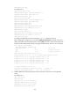
After completing the configurations, execute the display bgp peer ipv6 vpn-instance command on
the PEs. BGP peer relationships have been established between PEs and CEs, and have reached
Established state.
Take PE 1 as an example:
[PE1] display bgp peer ipv6 vpn-instance vpn1
BGP local router ID : 1.1.1.9
Local AS number : 100
Total number of peers : 1 Peers in established state : 1
Peer AS MsgRcvd MsgSent OutQ PrefRcv Up/Down State
2001:1::1 65410 5 5 0 1 00:02:03 Established
5. Configure an MP-IBGP peer relationship between the PEs:
# Configure PE 1.
[PE1] bgp 100
[PE1-bgp] peer 2.2.2.9 as-number 100
[PE1-bgp] peer 2.2.2.9 connect-interface loopback 0
[PE1-bgp] address-family vpnv6
[PE1-bgp-vpnv6] peer 2.2.2.9 enable
[PE1-bgp-vpnv6] quit
[PE1-bgp] quit
# Configure PE 2 in the same way that PE 1 is configured. (Details not shown.)
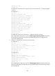
After completing the configuration, execute the display bgp peer vpnv6 command on the PEs. A
BGP peer relationship has been established between the PEs, and has reached Established state.
[PE1] display bgp peer vpnv6
BGP local router ID : 1.1.1.9
Local AS number : 100
Total number of peers : 1 Peers in established state : 1
Peer AS MsgRcvd MsgSent OutQ PrefRcv Up/Down State
2.2.2.9 100 3 3 0 1 00:00:34 Established
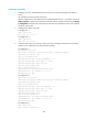
6. Configure a GRE tunnel:
# Configure PE 1.
[PE1] interface tunnel 0 mode gre
[PE1-Tunnel0] source loopback 0
[PE1-Tunnel0] destination 2.2.2.9
[PE1-Tunnel0] ip address 20.1.1.1 24
[PE1-Tunnel0] mpls enable
[PE1-Tunnel0] quit
# Configure PE 2.
[PE2] interface tunnel 0 mode gre
[PE2-Tunnel0] source loopback 0
[PE2-Tunnel0] destination 1.1.1.9
[PE2-Tunnel0] ip address 20.1.1.2 24
[PE2-Tunnel0] mpls enable
[PE2-Tunnel0] quit