
HP MSR2000/3000/4000 Router Series MPLS Configuration Guide


252
Verifying the configuration
The CEs have learned the route to each other and can ping each other.
Configuring IPv6 MPLS L3VPN inter-AS option A
Network requirements
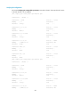
CE 1 and CE 2 belong to the same VPN. CE 1 accesses the network through PE 1 in AS 100 and CE 2
accesses the network through PE 2 in AS 200.
Configure IPv6 MPLS L3VPN inter-AS option A, and use VRF-to-VRF method to manage VPN routes.
Run OSPF on the MPLS backbone of each AS.
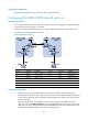
Figure 64 Network diagram
Device Interface IP address
Device
Interface IP address
CE 1 Eth1/1 2001:1::1/96
CE 2
Eth1/1 2001:2::1/96
PE 1 Loop0 1.1.1.9/32 PE 2 Loop0 4.4.4.9/32
Eth1/1 2001:1::2/96
Eth1/1 2001:2::2/96
POS5/0 172.1.1.2/24
POS5/0 162.1.1.2/24
ASBR-PE1 Loop0 2.2.2.9/32 ASBR-PE2 Loop0 3.3.3.9/32
POS5/0 172.1.1.1/24
POS5/0 162.1.1.1/24
POS5/1 2002:1::1/96
POS5/1 2002:1::2/96
Configuration procedure
1. Configure an IGP on each MPLS backbone to ensure IP connectivity within the backbone:
This example uses OSPF. Be sure to advertise the route to the 32-bit loopback interface address of
each router through OSPF. Use the loopback interface address of a router as the router's LSR ID.
(Details not shown.)
After the configurations, each ASBR PE and the PE in the same AS can establish an OSPF
adjacency. Execute the display ospf peer command and ping command. The output shows that the
adjacencies are in Full state, and that the PE and ASBR PE in the same AS have learned the routes
to the loopback interfaces of each other and can ping each other.