
HP MSR2000/3000/4000 Router Series MPLS Configuration Guide

264
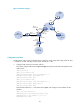
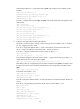
PE 1 Loop0 3.3.3.9/32
PE 2
Loop0
4.4.4.9/32
POS5/0 11.1.1.2/24 POS5/0 30.1.1.2/24
POS5/1 30.1.1.1/24
POS5/1
21.1.1.1/24
Configuration procedure
1. Configure MPLS L3VPN on the provider carrier backbone. Start IS-IS as the IGP, enable LDP on PE
1 and PE 2, and establish an MP-IBGP peer relationship between the PEs:
# Configure PE 1.
<PE1> system-view
[PE1] interface loopback 0
[PE1-LoopBack0] ip address 3.3.3.9 32
[PE1-LoopBack0] quit
[PE1] mpls lsr-id 3.3.3.9
[PE1] mpls ldp
[PE1-ldp] quit
[PE1] isis 1
[PE1-isis-1] network-entity 10.0000.0000.0000.0004.00
[PE1-isis-1] quit
[PE1] interface loopback 0
[PE1-LoopBack0] isis enable 1
[PE1-LoopBack0] quit
[PE1] interface pos 5/1
[PE1-POS5/1] ip address 30.1.1.1 24
[PE1-POS5/1] isis enable 1
[PE1-POS5/1] mpls enable
[PE1-POS5/1] mpls ldp enable
[PE1-POS5/1] mpls ldp transport-address interface
[PE1-POS5/1] quit
[PE1] bgp 100
[PE1-bgp] peer 4.4.4.9 as-number 100
[PE1-bgp] peer 4.4.4.9 connect-interface loopback 0
[PE1-bgp] address-family vpnv4
[PE1-bgp-vpnv4] peer 4.4.4.9 enable
[PE1-bgp-vpnv4] quit
[PE1-bgp] quit
# Configure PE 2 in the same way that PE 1 is configured. (Details not shown.)
After you complete the configurations, execute the display mpls ldp peer command on PE 1 or PE
2 to see that the LDP session has been established. Execute the display bgp peer vpnv4 command
and you can see that the BGP peer relationship has been established and has reached the
Established state. Execute the display isis peer command to see that an IS-IS neighbor relationship
has been set up. Take PE 1 as an example:
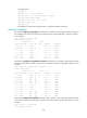
[PE1] display mpls ldp peer
Total number of peers: 1
Peer LDP ID State LAM Role GR MD5 KA Sent/Rcvd
4.4.4.9:0 Operational DU Active Off Off 8/8
[PE1] display bgp peer vpnv4