
HP MSR2000/3000/4000 Router Series MPLS Configuration Guide

271
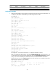
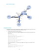
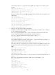
Figure 67 Network diagram
Configuration procedure
Assume that the system name of the MCE device is MCE, the system names of the edge routers of VPN
1 and VPN 2 are VR1 and VR2, and the system name of PE 1 is PE1.
1. Configure VPN instances on the MCE and PE 1:
# On MCE, configure VPN instances vpn1 and vpn2, and specify an RD and route targets for each
VPN instance.
<MCE> system-view
[MCE] ip vpn-instance vpn1
[MCE-vpn-instance-vpn1] route-distinguisher 10:1
[MCE-vpn-instance-vpn1] vpn-target 10:1
[MCE-vpn-instance-vpn1] quit
[MCE] ip vpn-instance vpn2
[MCE-vpn-instance-vpn2] route-distinguisher 20:1
[MCE-vpn-instance-vpn2] vpn-target 20:1
[MCE-vpn-instance-vpn2] quit
# Bind interface Ethernet 1/1 with VPN instance vpn1, and configure an IPv6 address for the
interface.
[MCE] interface ethernet 1/1
[MCE-Ethernet1/1] ip binding vpn-instance vpn1
[MCE-Ethernet1/1] ipv6 address 2001:1::1 64
[MCE-Ethernet1/1] quit
CE
VPN 1
Site 2
CE
VPN 2
Site 1
PE 1
PE 3
PE 2
VPN 2
2012::/64
VR 2
VPN 1
2012:1::/64
VR 1
MCE
Eth1/1
2001:1::1/64
Eth1/1.1
2001:2::4/64
Eth1/3.1
2001:2::3/64
Eth1/2
2002:1::1/64
Eth1/2
2001:1::2/64
Eth1/2
2002:1::2/64
Eth1/1
2012:1::2/64
Eth1/1
2012::2/64
Eth1/3.2
2002:2::3/64
Eth1/1.2
2002:2::4/64