
HP MSR2000/3000/4000 Router Series MPLS Configuration Guide


50
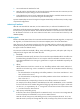
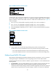
Figure 22 RDM bandwidth constraints model
In MAM model, a BC constrains the bandwidth for only one CT. This ensures bandwidth isolation among
CTs no matter whether preemption is used or not. Compared with RDM, MAM is easier to configure.
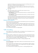
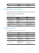
MAM is suitable for networks where traffic of each CT is stable and no traffic bursts occur. Figure 23
sh
ows an example:
• BC 0 is for CT 0. The bandwidth occupied by the traffic of CT 0 cannot exceed BC 0.
• BC 1 is for CT 1. The bandwidth occupied by the traffic of CT 1 cannot exceed BC 1.
• BC 2 is for CT 2. The bandwidth occupied by the traffic of CT 2 cannot exceed BC 2.
• The total bandwidth occupied by CT 0, CT 1, and CT 2 cannot exceed the maximum reservable
bandwidth.
Figure 23 MAM bandwidth constraints model
3. Checks whether the CT and the LSP setup/holding priority match an existing TE class.
An MPLS TE tunnel can be established for the CT only when the following conditions are met:
{ Every node along the tunnel has a TE class that matches the CT and the LSP setup priority.
{ Every node along the tunnel has a TE class that matches the CT and the LSP holding priority.
Bidirectional MPLS TE tunnel
MPLS Transport Profile (MPLS-TP) uses bidirectional MPLS TE tunnels to implement 1:1 and 1+1 protection
switching and support in-band detection tools and signaling protocols such as OAM and PSC.
A bidirectional MPLS TE tunnel includes two CRLSPs in opposite directions. It can be established in the
following modes:
• Co-routed mode—Uses the extended RSVP-TE protocol to establish a bidirectional MPLS TE tunnel.
RSVP-TE uses a Path message to advertise the labels assigned by the upstream LSR to the
downstream LSR and a Resv message to advertise the labels assigned by the downstream LSR to the
upstream LSR. During the delivery of the path message, a CRLSP in one direction is established.
CT 2
CT 1
CT 0
BC 0
Max reservable BW
BC 1
BC 2
CT 0 CT 1 CT 2