
HP MSR2000/3000/4000 Router Series MPLS Configuration Guide


78
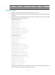
1.1.1.9/32 Direct 0 0 127.0.0.1 InLoop0
2.2.2.9/32 OSPF 10 1 10.1.1.2 Eth1/1
3.3.3.9/32 O_ASE 150 1 10.1.1.2 Eth1/1
4.4.4.9/32 O_ASE 150 1 10.1.1.2 Eth1/1
7.1.1.0/24 Direct 0 0 7.1.1.1 Tun1
7.1.1.1/32 Direct 0 0 127.0.0.1 InLoop0
10.1.1.0/24 Direct 0 0 10.1.1.1 Eth1/1
10.1.1.1/32 Direct 0 0 127.0.0.1 InLoop0
20.1.1.0/24 O_ASE 150 1 10.1.1.2 Eth1/1
30.1.1.0/24 Static 1 0 7.1.1.1 Tun1
127.0.0.0/8 Direct 0 0 127.0.0.1 InLoop0
127.0.0.1/32 Direct 0 0 127.0.0.1 InLoop0
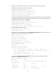
FRR configuration example
Network requirements
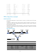
On the primary CRLSP Router A—Router B—Router C—Router D, use FRR to protect the link Router
B—Router C.
Use RSVP-TE to establish the primary CRLSP and bypass CRLSP of the MPLS TE tunnel based on the
constraints of the explicit paths. The bypass CRLSP uses path Router B—Router E—Router C. Router B is
the PLR and Router C is the MP.
Configure BFD for RSVP-TE between Router B and Router C. When the link between Router B and Router
C fails, BFD can detect the failure quickly and notify RSVP-TE of the failure, so RSVP-TE can switch traffic
to the bypass CRLSP.
Figure 26 Network diagram
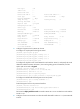
Device
Interface IP address Device Interface IP address
Router A Loop0 1.1.1.1/32 Router E Loop0 5.5.5.5/32
Eth1/1 2.1.1.1/24
POS5/0
3.2.1.2/24
Router B Loop0 2.2.2.2/32
POS5/1
3.3.1.1/24
Eth1/1 2.1.1.2/24 Router C Loop0 3.3.3.3/32
Eth1/2 3.1.1.1/24
Eth1/1
4.1.1.1/24
POS5/0 3.2.1.1/24
Eth1/2
3.1.1.2/24
Router D Loop0 4.4.4.4/32 POS5/0 3.3.1.2/24