
HP MSR2000/3000/4000 Router Series MPLS Configuration Guide


83
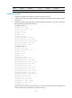
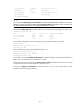
Reoptimization : Disabled Reoptimization Freq : -
Backup Type : None Backup LSP ID : -
Auto Bandwidth : Disabled Auto Bandwidth Freq : -
Min Bandwidth : - Max Bandwidth : -
Collected Bandwidth : -
NOTE:
If you execute the display mpls te tunnel-interface command immediately after an FRR, you can see two
CRLSPs in up state. This is because FRR uses the make-before-break mechanism to set up a new LSP, and
the old LSP is deleted after the new one has been established for a while.
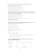
# Execute the display mpls lsp command on Router B. The output shows that the bypass tunnel is in use.
[RouterB] display mpls lsp
FEC Proto In/Out Label Interface/Out NHLFE
1.1.1.1/4/18753 RSVP 1122/3 Tun5
2.2.2.2/5/40312 RSVP -/1150 GE0/1/4
3.2.1.2 Local -/- GE0/1/4
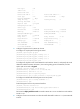
# On the PLR, configure the interval for selecting an optimal bypass tunnel as 5 seconds.
[RouterB] rsvp
[RouterB-rsvp] fast-reroute timer 5
[RouterB-rsvp] quit
# On the PLR, bring up the protected interface Ethernet 1/2.
[RouterB] interface ethernet 1/2
[RouterB-Ethernet1/2] undo shutdown
[RouterB-Ethernet1/2] quit
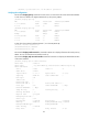
# On Router A, execute the display interface tunnel 4 command to display information about the primary
CRLSP. You can see that the tunnel interface is in up state.
# Wait for about 5 seconds, execute the display mpls lsp verbose command on Router B. You can see
that Tunnel5 is bound to interface Ethernet 1/2 but not in use.
# Execute the display ip routing-table command on Router A. You can see a static route entry with
interface Tunnel4 as the egress interface.