
HP MSR2000/3000/4000 Router Series Network Management and Monitoring Configuration Guide


99
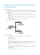
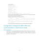
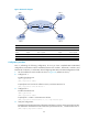
Figure 38 Network diagram
Device Interface IP address
Device
Interface IP address
CE 1 S2/0 10.1.1.1/24 PE 1 S2/0 10.1.1.2/24
CE 2
CE 3
S2/0
S2/0
10.2.1.1/24
10.3.1.1/24
S2/1
S2/2
172.1.1.1/24
10.2.1.2/24
CE 4 S2/0 10.4.1.1/24
PE 2
S2/0
10.3.1.2/24
P S2/0 172.1.1.2/24
S2/1
172.2.1.2/24
S2/1 172.2.1.1/24 S2/2 10.4.1.2/24
Configuration procedure
Prior to performing the following configuration, be sure you have completed MPLS VPN-related
configurations, and make sure of the reachability between CE 1 and PE 1, between PE 1 and PE 2, and
between PE 2 and CE 3. For information about configuring MPLS VPN, see MPLS Configuration Guide.
1. Set the IP address for each interface as shown in Figure 38. (Details
not shown.)
2. Configure CE 1:
# Enable the NTP service.
<CE1> system-view
[CE1] ntp-service enable
# Specify the local clock as the reference source, with the stratum level 2.
[CE1] ntp-service refclock-master 2
3. Configure PE 2:
# Enable the NTP service.
<PE2> system-view
[PE2] ntp-service enable
# Specify CE 1 in VPN 1 as the NTP server of PE 2.
[PE2] ntp-service unicast-server 10.1.1.1 vpn-instance vpn1
4. Verify the configuration:
# Display the IPv4 NTP association information and status on PE 2 a certain period of time later.
The information should show that PE 2 has been synchronized to CE 1, with the stratum level 3.
[PE2] display ntp-service status
CE 1
CE 2 CE 4
CE 3
PE 1 PE 2P
VPN 1
VPN 2
VPN 1
VPN 2
S2/0
S2/0
S2/2
S2/0
S2/1 S2/1
S2/0 S2/0
S2/0
S2/0
S2/2
S2/1
MPLS backbone