
HP MSR2000/3000/4000 Router Series Network Management and Monitoring Configuration Guide


80
Displaying and maintaining NTP
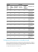
Execute display commands in any view.
Task Command
Display information about NTP service status. display ntp-service status
Display information about IPv4 NTP associations. display ntp-service sessions [ verbose ]
Display information about IPv6 NTP associations. display ntp-service ipv6 sessions [ verbose ]
Display brief information about the NTP servers from
the local device back to the primary reference source.
display ntp-service trace
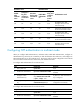
NTP client/server mode configuration example
Network requirements
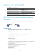
As shown in Figure 29, the local clock of Device A is to be used as a reference source, with the stratum
level 2. Device B operates in client mode and Device A is to be used as the NTP server for Device B.
Figure 29 Network diagram
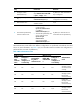
Configuration procedure
1. Set the IP address for each interface as shown in Figure 29. (Details not shown.)
2. Configure Device A:
# Enable the NTP service.
<DeviceA> system-view
[DeviceA] ntp-service enable
# Specify the local clock as the reference source, with the stratum level 2.
[DeviceA] ntp-service refclock-master 2
3. Configure Device B:
# Enable the NTP service.
<DeviceB> system-view
[DeviceB] ntp-service enable
# Specify Device A as the NTP server of Device B so that Device B is synchronized to Device A.
[DeviceB] ntp-service unicast-server 1.0.1.11
4. Verify the configuration:
# Display the NTP status of Device B after clock synchronization.
[DeviceB] display ntp-service status
Clock status: synchronized
Clock stratum: 3
System peer: 1.0.1.11