
HP MSR2000/3000/4000 Router Series Network Management and Monitoring Configuration Guide


85
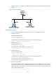
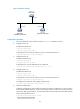
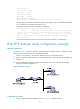
Figure 32 Network diagram
Configuration procedure
1. Set the IP address for each interface as shown in Figure 32. (Details not shown.)
2. Configure Device A:
# Enable the NTP service.
<DeviceA> system-view
[DeviceA] ntp-service enable
# Specify the local clock as the reference source, with the stratum level 3.
[DeviceA] ntp-service refclock-master 3
3. Configure Device B:
# Enable the NTP service.
<DeviceB> system-view
[DeviceB] ntp-service enable
# Specify Device A as the IPv6 NTP server of Device B.
[DeviceB] ntp-service ipv6 unicast-server 3000::34
4. Configure Device C:
# Enable the NTP service.
<DeviceC> system-view
[DeviceC] ntp-service enable
# Specify the local clock as the reference source, with the stratum level 2.
[DeviceC] ntp-service refclock-master 2
# Configure Device B as an IPv6 symmetric passive peer.
[DeviceC] ntp-service ipv6 unicast-peer 3000::35
5. Verify the configuration:
# After the configuration, Device B has two time servers Device A and Device C. Device C has a
lower stratum level than Device A, so Device B selects Device C as a reference clock to synchronize
to Device C. After synchronization, view the status of Device B. The output shows that Device B has
been synchronized to Device C.
[DeviceB] display ntp-service status
Clock status: synchronized
Device A
NTP server
Device B
NTP client/
symmetric passive peer
Device C
Symmetric active peer
3000::34/64
3000::35/64 3000::36/64