
HP MSR2000/3000/4000 Router Series Network Management and Monitoring Configuration Guide


87
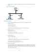
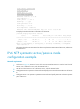
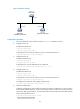
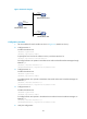
Figure 33 Network diagram
Configuration procedure
1. Set the IP address for each interface as shown in Figure 33. (Details not shown.)
2. Configure Router C:
# Enable the NTP service.
<RouterC> system-view
[RouterC] ntp-service enable
# Specify the local clock as the reference source, with the stratum level 2.
[RouterC] ntp-service refclock-master 2
# Configure Router C to operate in broadcast server mode and send broadcast messages through
Ethernet 1/1.
[RouterC] interface ethernet 1/1
[RouterC-Ethernet1/1] ntp-service broadcast-server
3. Configure Router A:
# Enable the NTP service.
<RouterA> system-view
[RouterA] ntp-service enable
# Configure Router A to operate in broadcast client mode and receive broadcast messages on
Ethernet 1/1.
[RouterA] interface ethernet 1/1
[RouterA-Ethernet1/1] ntp-service broadcast-client
4. Configure Router B:
# Enable the NTP service.
<RouterB> system-view
[RouterB] ntp-service enable
# Configure Router B to operate in broadcast client mode and receive broadcast messages on
Ethernet 1/1.
[RouterB] interface ethernet 1/1
[RouterB-Ethernet1/1] ntp-service broadcast-client
5. Verify the configuration:
Eth1/1
3.0.1.31/24
Eth1/1
3.0.1.32/24
Router A
NTP broadcast client
Router C
NTP broadcast server
Router B
NTP broadcast client
Eth1/1
3.0.1.30/24