
HP MSR2000/3000/4000 Router Series Network Management and Monitoring Configuration Guide


89
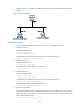
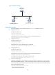
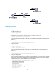
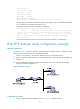
Figure 34 Network diagram
Configuration procedure
1. Set the IP address for each interface as shown in Figure 34. (Details not shown.)
2. Configure Router C:
# Enable the NTP service.
<RouterC> system-view
[RouterC] ntp-service enable
# Specify the local clock as the reference source, with the stratum level 2.
[RouterC] ntp-service refclock-master 2
# Configure Router C to operate in multicast server mode and send multicast messages through
Ethernet 1/1.
[RouterC] interface ethernet 1/1
[RouterC-Ethernet1/1] ntp-service multicast-server
3. Configure Router D:
# Enable the NTP service.
<RouterD> system-view
[RouterD] ntp-service enable
# Configure Router D to operate in multicast client mode and receive multicast messages on
Ethernet 1/1.
[RouterD] interface ethernet 1/1
[RouterD-Ethernet1/1] ntp-service multicast-client
4. Verify the configuration:
# Because Router D and Router C are on the same subnet, Router D can receive multicast messages
from Router C without being enabled with the multicast function and can synchronize to Router C.
Display the NTP status of Router D after clock synchronization.
[RouterD-Ethernet1/1] display ntp-service status
Clock status: synchronized
Clock stratum: 3
System peer: 3.0.1.31
Local mode: bclient
Reference clock ID: 3.0.1.31
Leap indicator: 00