HP MSR2000/3000/4000 Router Series Voice Configuration Guide (V7) Part number: 5998-3997 Software version: CMW710-R0007P02 Document version: 6PW100-20130927
Legal and notice information © Copyright 2013 Hewlett-Packard Development Company, L.P. No part of this documentation may be reproduced or transmitted in any form or by any means without prior written consent of Hewlett-Packard Development Company, L.P. The information contained herein is subject to change without notice.
Contents Configuring analog voice interfaces ·························································································································· 1 FXS interface ······································································································································································ 1 FXO interface··················································································································································
Configuring a TDM clock source ························································································································· 30 Configuring other parameters ······························································································································ 31 Configuring basic parameters for a T1 interface ······································································································· 31 Configuring a TDM clock source ···········
Configuring number substitution ··································································································································· 66 Number substitution on the calling router ··········································································································· 67 Number substitution on the called router ············································································································ 68 Configuring global number substitution
Displaying and maintaining SIP trunk ························································································································ 100 SIP trunk configuration examples ······························································································································· 101 Configuring call services ········································································································································ 103 Call waiting·····
Configuring analog voice interfaces Analog voice interfaces include FXS, FXO, and E&M interfaces. FXS interface A Foreign Exchange Station (FXS) interface connects to a standard telephone, fax machine, or a Private Branch Exchange (PBX) through an RJ-11 connector and a telephone cable. It provides ring, voltage, and dial tone based on level changes on the Tip/Ring line. An FXS interface can only connect to an FXO interface.
Tasks at a glance (Optional.) Configuring an FXO interface • • • • • • • Configuring CID Configuring busy tone detection Configuring an on-hook delay Configuring the off-hook mode Configuring ring detection parameters Setting the electrical impedance Configuring the packet loss compensation mode (Optional.) Binding an FXS interface to an FXO interface (Optional.
Step Command Remarks 1. Enter system view. system-view N/A 2. Enter voice view. voice-setup N/A • Specify a country: cptone country-type locale • Customize call progress tone 3. 4. Configure call progress tones. Configure the amplitude value for call progress tones.
• To ensure correct call time, make sure the router system time transmitted in data-message format stays synchronous with the local standard time. • For the CID function to operate correctly, keep the cid send command enabled. Configuration procedure Step Command Remarks 1. Enter system view. system-view N/A 2. Enter FXS interface view. subscriber-line line-number N/A 3. (Optional.) Configure the calling name for the FXS interface. By default, no calling name is configured. 4.
Step Enter FXS interface view. 2. Set the electrical impedance of a country. 3. Command Remarks subscriber-line line-number N/A impedance { country-name | r550 | r600 | r650 | r700 | r750 | r800 | r850 | r900 | r950 } The default is the electrical impedance of China. You must configure the same electrical impedance value on the originating and terminating devices.
Configuring an FXO interface This section covers the procedures for configuring an FXO interface. Configuring CID The CID function must be configured on both the FXS and FXO interfaces. For information about configuring this function on the FXS interface, see "Configuring CID." For the CID function to work correctly, enable both CID receiving and CID sending. Enabling CID receiving for an FXO interface The FXO interface receives the CID.
Figure 1 Busy tone detection You can configure busy tone detection by customizing busy tone parameters or configuring automatic busy tone detection. If the tone that the router receives from the PBX matches the busy tone parameters, the router considers the tone as a busy tone and shuts down the FXO interface. Configuring a busy tone standard Two busy tone standards are available: European standard and North American standard.
2. Telephone A first goes on-hook. The PBX plays busy tones to Router A after detecting the on-hook condition. 3. Execute the busytone-detect auto command on Router A to detect the busy tone. To make sure the FXO interface can capture the busy tone sent by the PBX, HP recommends that you execute this command two seconds after Telephone A goes on-hook. 4. The console prompts that busy tone detection is in progress and prompts detection success when the detection is complete. 5.
To configure silence detection-based automatic on-hook: Step Command Remarks 1. Enter system view. system-view N/A 2. Enter FXO interface view. subscriber-line line-number N/A 3. Configure silence detection-based automatic on-hook. silence-detect threshold threshold time time-length By default, the silence threshold is 20, and the silence duration f is 7200 seconds (2 hours).
Configuring the off-hook mode The FXO interface supports two off-hook modes: • Immediate mode—Upon receiving a call, the FXO interface goes off-hook and sends a dial tone to the calling party. Then, the calling party dials the destination number. • Delay mode—Upon receiving a call, the FXO interface places a call to the specified private line number. When the called party picks up the phone, the FXO goes off-hook. This mode needs to work with the private line auto ring-down (PLAR) function.
Setting the electrical impedance The electrical impedance setting must be subject to country specifications. Each country corresponds to an impedance value. You specify an impedance value while specifying a country. To set the electrical impedance: Step Command Remarks 1. Enter system view. system-view N/A 2. Enter FXO interface view. subscriber-line line-number N/A Set the electrical impedance of a country. 3.
Step Command Remarks 2. Enter FXO interface view. subscriber-line line-number N/A 3. Bind an FXS interface to the FXO interface. hookoff-mode delay bind fxs_subscriber_line [ ring-immediately ] By default, no FXS interface is bound. By default, the PLAR function is disabled. 4. Enable the PLAR function. private-line string For more information about this command, see Voice Command Reference. 5. Configure the interval between on-hook and off-hook.
• Immediate start—After off-hook, the originating side waits for a specified period of time to send the called number to the terminating side. During this period of time, the originating side does not check whether the terminating side is ready to receive the called number. The terminating side enters off-hook state after receiving the called number. Figure 3 Immediate start • Delay start—The originating side goes off-hook and seizes the trunk.
Figure 5 Wink start To configure the immediate start mode: Step Command Remarks 1. Enter system view. system-view N/A 2. Enter E&M interface view. subscriber-line line-number N/A 3. Configure the immediate start mode for the E&M interface. signal immediate The default is the immediate start mode. 4. Configure a delay the originating side waits to send DTMF tones in immediate start mode. delay send-dtmf milliseconds The default is 300 milliseconds.
Step Command Remarks 2. Enter voice interface view. subscriber-line line-number N/A 3. Configure the wink start mode for the E&M interface. signal wink The default is the immediate start mode. 4. Configure the delay time from when the terminating side receives a seizure signal to when it sends a wink signal in the wink start mode. delay send-wink milliseconds 5. 6. Configure the duration of a wink signal sent by the terminating side in wink start mode.
Enabling E&M control signals pass-through This feature operates only when the E&M non-signaling mode is enabled. As shown in Figure 6, an E&M virtual private line is set up between the tone generator and the radio. Enable E&M control signals pass-through for Router A and Router B so that they can send seize and idle signals for the E&M virtual line over the IP network. Figure 6 E&M analog control signals pass-through To enable E&M control signals pass-through: Step Command Remarks 1. Enter system view.
Figure 7 DTMF keypad frequencies Column Frequency Group 1209Hz 1336Hz 1477Hz 1633Hz 697Hz 1 2 3 A 770Hz 4 5 6 B 852Hz 7 8 9 C 941Hz * 0 # D A DTMF tone must last at least 45 milliseconds. A minimum interval of 23 milliseconds is required between two DTMF tones to make sure DTMF tones are recognizable. Such requirements are roughly the same in all countries. For more information, see the ITU-T Recommendation Q.24. Configuring DTMF tone sending Step Command Remarks 1.
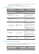
Step Command Remarks 1. Enter system view. system-view N/A 2. Enter voice interface view. subscriber-line line-number N/A 3. 4. Configure the threshold parameters for DTMF detection. dtmf threshold analog index value Configure the DTMF detection sensitivity level. dtmf sensitivity-level { high | low | medium [ frequency-tolerance value ] } By default, indexes 0 to 12 correspond to 1400, 458, -9, -9, -9, -9, -3, -12, -12, 30, 300, 3200, and 375, respectively.
Step 3. 4. 5. Command Remarks The default is 10 seconds. Configure the interval between off-hook and dialing the first digit. timer first-dial seconds This command applies only to FXO and FXS interfaces. Configure the maximum interval for dialing the next digit. timer dial-interval seconds The default is 10 seconds. Configure the maximum duration for playing ringback tones. timer ring-back seconds The default is 60 seconds. The default is 1 second. 6. 7. Configure the dial delay time.
the echo cancellation delay (the time between when an interface sends out a signal and when to the interface receives an echo) to 33 ms and the echo cancellation coverage to 16 ms. Figure 8 Echo Configuring the echo cancellation function Step Command Remarks 1. Enter system view. system-view N/A 2. Enter voice interface view. subscriber-line line-number N/A 3. Enable the echo cancellation function. echo-canceler enable By default, this function is enabled. 4.
Step 2. 3. Enter voice view. Adjust echo cancellation parameters. Command Remarks voice-setup N/A echo-canceler { convergence-rate value | max-amplitude value | mix-proportion-ratio value | talk-threshold value } By default, the convergence rate of comfort noise amplitude is 0, the maximum amplitude of comfort noise is 256, the comfort noise mixture proportion control factor is 100, and the two-way judgment threshold is 1.
Configure the two routers to enable Telephone B to establish a call with Telephone A through two dials. Figure 9 Network diagram Eth2/1 1.1.1.1/24 FXS 1/0 Telephone A 0101001 IP network Eth2/1 2.2.2.2/24 FXO 1/0 Router B Router A PBX Telephone B 07552001 Configuration procedure 1. On Router A, configure the local number as 0101001 for POTS entity 1001, and bind FXS interface line1/0 to the POTS entity.
Configure PLAR for the FXO interface of Router B. When the user of Telephone B dials 07552003, the FXO interface automatically calls Telephone A. Figure 10 Network diagram Eth2/1 1.1.1.1/24 FXS 1/0 Telephone A 0101001 IP network Eth2/1 2.2.2.2/24 FXO 1/0 Router B Router A PBX Telephone B 07552001 Configuration procedure 1. On Router A, configure the local number as 0101001 for POTS entity 1001, and bind FXS interface line1/0 to the POTS entity.
E&M interface configuration example Network requirements As shown in Figure 11, Router A and Router B are connected through an IP network and can reach each other. Configure the two routers to enable Telephone A and Telephone B to establish calls. Figure 11 Network diagram Eth2/1 1.1.1.1/24 FXS 1/0 Telephone A 0101001 IP network Eth2/1 2.2.2.2/24 Router A E&M 5/0 Router B PBX Telephone B Configuration procedure 1.
# Enter the view of E&M interface 5/0. The E&M interface must have the same configuration as the connected PBX. system-view [RouterB] subscriber-line 5/0 # Configure the wink start mode. [RouterB-subscriber-line5/0] signal wink # Configure the 4-wire cable type (optional, because the default is the 4-wire cable type). [RouterB-subscriber-line5/0] cable 4-wire # Configure the signal type as 5 (optional, because the default is 5).
[RouterA-voice-dial] entity 1000 pots [RouterA-voice-dial-entity1000] match-template 1000 [RouterA-voice-dial-entity1000] line 5/0 [RouterA-voice-dial-entity1000] return # Enter the view of E&M interface 5/0. system-view [RouterA] subscriber-line 5/0 # Configure the immediate start mode (optional, because the default is the immediate start mode). [RouterA-subscriber-line5/0] signal immediate # Enable the PLAR function.
Verifying the configuration After the user of Telephone A picks up the handset, Router A automatically calls Telephone B. After the user of Telephone B picks up the handset, the two users can establish a conversation. FXS&FXO 1:1 binding configuration example Network requirements As shown in Figure 12, Telephone A calls Telephone B through the IP network. When the IP network is unavailable, Telephone A uses the bound FXO interface to call Telephone B through the PSTN network.
[RouterA-voice-dial] quit [RouterA-voice] quit # Enable the PLAR function for the FXO interface line 2/0, and bind the FXS interface line 1/0 to the FXO interface line 2/0. [RouterA] subscriber-line 2/0 [RouterA-subscriber-line2/0] private-line 0101001 [RouterA-subscriber-line2/0] hookoff-mode delay bind 1/0 2. Configure Router B: # Configure the called number template as 010…. for VoIP entity 010, and configure the destination IP address as 192.168.0.71.
Configuring digital voice interfaces Digital voice interfaces include E1, T1, and BSV interfaces. E1 and T1 interfaces E1 interfaces (also called VE1 interfaces) and T1 interfaces (also called VT1 interfaces) can connect to the PSTN as trunk interfaces. An E1 interface provides 32 timeslots and 2.048 Mbps bandwidth. A T1 interface provides 24 timeslots and 1.544 Mbps bandwidth. ITU-T E1 is used mainly in Europe and China. ANSI T1 is used mainly in America, Canada, and Japan.
Tasks at a glance (Required.) Perform one of the following tasks: • Configuring R2 signaling { Configuring basic R2 signaling parameters { Configuring R2 digital line signaling { Configuring R2 interregister signaling • Configuring the ISDN protocol (Required.) Binding a digital voice interface to a POTS entity To configure BSV interfaces, perform the following tasks: Tasks at a glance (Required.
Step Command Remarks 1. Enter system view. system-view N/A 2. Enter E1 interface view. controller e1 number N/A 3. Configure a TDM clock source for the E1 interface. tdm-clock { internal | line [ primary ] } The default is internal. Configuring other parameters Step Command Remarks 1. Enter system view. system-view N/A 2. Enter E1 interface view. controller e1 number N/A 3. Configure a description. description text The default is interface name Interface. 4.
Step Configure a TDM clock source for the T1 interface. 3. Command Remarks tdm-clock { internal | line [ primary ] } The default is internal. Configuring other parameters Step Command Remarks 1. Enter system view. system-view N/A 2. Enter T1 interface view. controller t1 number N/A 3. Configure a description. description text The default is interface name Interface. 4. Configure the framing format. frame-format { esf | sf } The default is esf. 5. Set the line coding format.
subinterfaces, but you can use the display voice subscriber-line line-number.subnumber command to view the call state of a subinterface. Configuring a BRI interface Step Command Remarks 1. Enter system view. system-view N/A 2. Enter BRI interface view. interface bri interface-number N/A 3. (Optional.) Configure a description for the interface. description text The default is interface name Interface. 4. (Optional.) Enable loopback detection for B channels.
Step Command Remarks 1. Enter system view. system-view N/A 2. Enter E1 or T1 interface view. controller { e1 | t1 } number N/A 3. Create a timeslot set and enable R2 signaling for it. timeslot-set ts-set-number timeslot-list timeslots-list signal r2 By default, no timeslot set is created. Configuring a logical digital voice interface The system automatically creates a logical voice interface in the form of E1/T1 interface number:timeslot set number for a timeslot set.
R2 signaling include two categories: digital line signaling and interregister signaling. Digital line signaling conveys status information about E1 trunks to describe whether the trunks are seized, released, or blocked. Interregister signaling transmits and requests calling and called numbers. ITU-T digital line signaling Digital line signaling monitors the state of a trunk and controls calls. It can identify the following state changes: • The calling party goes off-hook and seizes the line.
When the circuit is idle, the originating side sends a forward seizure signal (00) to the terminating side, and the terminating side sends back a seizure acknowledgement signal (11). Then the circuit is seized, and interregister signaling exchange begins. When the called party picks up the phone, the terminating side sends a backward answer signal (01). After the originating side recognizes the received signal, it establishes the call. Figure 16 Call establishment • Call release at the originating side.
Blocking in idle state or during conversation. • After the originating side receives a blocking signal 11 from the terminating side when the circuit is idle or during conversation, the circuit is blocked. In this case, the originating side still sends the forward signal 10 to indicate that the line is idle. When the terminating side unblocks the circuit, it sends a backward signal 10 to indicate that the line is idle.
Designation Basic Meaning A-12 Send language or discrimination digit A-13 Send nature of circuit A-14 Request for information on use of an echo canceller (is an incoming half-echo suppressor required?) A-15 Congestion in an international exchange; terminate interregister signaling interaction or at its output Group II forward signals—Identify the calling party category. The system looks at the calling party category to decide whether the calling party can perform forced release or break-in.
Figure 19 shows the exchange process requesting calling party information, which is typical of R2 interregister signaling.
Configuring the trunk direction and routing mode Step Command Remarks 1. Enter system view. system-view N/A 2. Enter E1 or T1 interface view. controller { e1 | t1 } number N/A 3. Create a timeslot set and enable R2 signaling for it. timeslot-set ts-set-number timeslot-list timeslots-list signal r2 By default, no timeslot set is created. 4. Enter R2 CAS view. cas ts-set-number N/A The default is dual. 5. Configure the trunk direction.
Enabling DTMF to receive and send numbers R2 signaling has two modes to send and receive numbers: • MFC—The originating and terminating sides use interregister signaling to transmit and request number information, including the calling number, line information, and billing. In the exchange process, the terminating side sends responses to the originating side. • DTMF—The originating side transmits the called number to the terminating side digit by digit. The terminating side does not send any responses.
Step 5. Configure the connection mode. Command Remarks callmode { terminal | segment } By default, the terminal mode is used. Maintaining specified timeslots Step Command Remarks 1. Enter system view. system-view N/A 2. Enter E1 or T1 interface view. controller { e1 | t1 } number N/A 3. Create a timeslot set and enable R2 signaling for it. timeslot-set ts-set-number timeslot-list timeslots-list signal r2 By default, no timeslot set is created. 4. Enter R2 CAS view.
Step Command Remarks 11. Configure the C and D signal bits. renew ABCD The default depends on the R2 signaling standard (configured by using the mode command). 12. Configure line signal inversion mode. reverse ABCD The default is 0000, that is, line signal inversion is disabled. By default, the timeout time is: • 60000 milliseconds for answer 13. Set the timeout time of line signals. timer dl { answer | clear-back | clear-forward | | re-answer | release-guard | seizing } time signals.
Step Command Remarks 10. Configure interregister signal values.
Binding a digital voice interface to a POTS entity Step Command Remarks 1. Enter system view. system-view N/A 2. Enter voice view. voice-setup N/A 3. Enter voice dial program view. dial-program N/A 4. Create a POTS entity and enter POTS entity view. entity entity-number pots N/A • For E1 and T1 interfaces: 5. Bind a digital voice interface to the POTS entity.
Figure 20 Network diagram Configuration procedure 1. Configure Router A: # Configure the IP address 1.1.1.1/24 for interface GigabitEthernet 0/0. system-view [RouterA] interface GigabitEthernet 0/0 [RouterA-GigabitEthernet0/0] ip address 1.1.1.1 255.255.255.0 [RouterA-GigabitEthernet0/0] quit # Create a timeslot set on interface E1 5/0.
[RouterB-GigabitEthernet0/0] quit # Create a timeslot set on interface E1 5/0. [RouterB] controller e1 5/0 [RouterB-E1 5/0] timeslot-set 1 timeslot-list 1-31 signal r2 [RouterB-E1 5/0] quit # Configure the local number 07552001 for POTS entity 2001, and bind the digital voice interfaces line 5/0:1 to the POTS entity.
Figure 21 Network diagram Configuration procedure 1. Configure Router A: # Configure the IP address 1.1.1.1/24 for interface GigabitEthernet 0/0. system-view [RouterA] interface GigabitEthernet 0/0 [RouterA-GigabitEthernet0/0] ip address 1.1.1.1 255.255.255.0 [RouterA-GigabitEthernet0/0] quit # Bundle the timeslots on interface E1 5/0 into a PRI set.
[RouterB] interface GigabitEthernet 0/0 [RouterB-GigabitEthernet0/0] ip address 2.2.2.2 255.255.255.0 [RouterB-GigabitEthernet0/0] quit # Bundle the timeslots on interface E1 5/0 into a PRI set. [RouterB] controller e1 5/0 [RouterB-E1 5/0] pri-set [RouterB-E1 5/0] quit # Configure the local number 07552001 for POTS entity 2001, and bind the digital voice interfaces line 5/0:15 to the POTS entity.
Figure 22 Network diagram Configuration procedure 1. Configure Router A: # Configure the IP address 1.1.1.1/24 for interface GigabitEthernet 0/0. system-view [RouterA] interface GigabitEthernet 0/0 [RouterA-GigabitEthernet0/0] ip address 1.1.1.1 255.255.255.0 [RouterA-GigabitEthernet0/0] quit # Configure the local number 0101001 for POTS entity 1001, and bind the digital voice interfaces line 1/1 to the POTS entity.
# Configure the local number 07552001 for POTS entity 2001, and bind the digital voice interfaces line 1/1 to the POTS entity.
Configuring voice entities Overview Voice entities include POTS and VoIP entities: • POTS entity—A local POTS entity connects to a local telephone and maintains local number information. A trunk POTS entity connects to the PSTN and maintains call destination information. • VoIP entity—Connects to the IP side and maintains the called information such as the called number and call destination.. A VoIP entity can use SIP to make VoIP calls.
Creating a POTS entity and configuring basic parameters Step Command Remarks 1. Enter system view. system-view N/A 2. Enter voice view. voice-setup N/A 3. Enter dial program view. dial-program N/A 4. Create a POTS entity and enter POTS entity view. entity entity-number pots By default, no POTS voice entities exist. 5. (Optional.) Configure a description for the POTS entity. description string By default, no description is configured.
Step 5. Configure a codec for the POTS entity. Command Remarks codec { g711alaw | g711ulaw | g723r53 | g723r63 | g726r16 | g726r24 | g726r32 | g726r40 | g729a | g729br8 | g729r8 } [ bytes payload-size ] By default, no codecs are configured. To configure codecs for a POTS entity (method 2): Step Command Remarks 1. Enter system view. system-view N/A 2. Enter voice view. voice-setup N/A 3. Create a codec template. voice class codec tag By default, no codec templates exist.
Configuring DTMF for a POTS entity There are two ways to transmit DTMF tones: in-band signaling and out-of-band signaling. In-band signaling sends DTMF tones in RTP packets, and out-of-band signaling sends DTMF tones in SIP messages, or RFC 2883-compliant RTP messages (NTE mode). To use NTE mode, configure the outband nte command and the same payload type value on the originating and terminating sides. Otherwise, DTMF tones might fail to be transmitted.
Configuring options related to dial program Step Command Remarks 1. Enter system view. system-view N/A 2. Enter voice view. voice-setup N/A 3. Enter dial program view. dial-program N/A 4. Create a POTS entity and enter POTS entity view. entity entity-number pots N/A 5. Configure permitted calling numbers. caller-permit calling-string Optional. By default, the voice entity permits all calling numbers. Optional. Configure the priority of the POTS entity. priority priority-order 7.
Creating a VoIP entity and configuring basic parameters Step Command Remarks 1. Enter system view. system-view N/A 2. Enter voice view. voice-setup N/A 3. Enter dial program view. dial-program N/A 4. Create a VoIP entity and enter VoIP entity view. entity entity-number voip By default, no VoIP voice entities exist. 5. (Optional.) Configure a description for the VoIP entity. description string By default, no description is configured.
Step 5. Specify a codec for the VoIP entity. Command Remarks codec { g711alaw | g711ulaw | g723r53 | g723r63 | g726r16 | g726r24 | g726r32 | g726r40 | g729a | g729br8 | g729r8 } [ bytes payload-size ] By default, no codecs are configured. To configure codecs for a VoIP entity (method 2): Step Command Remarks 1. Enter system view. system-view N/A 2. Enter voice view. voice-setup N/A 3. Create a codec template. voice class codec tag By default, no codec templates exist.
Step Command Remarks • (Method 1) Configure NTE Use either method. mode: { 5. Configure out-of-band DTMF . { Enable NTE mode: outband nte Configure the value of the payload type used by NTE: rtp payload-type nte value • (Method 2) Configure SIP mode: outband sip By default, inband transmission is adopted, and the value of the payload type used by NTE is 101. When the device is connected to a device from another vendor, you cannot set the payload type field to any value forbidden by that device.
Step Command Remarks Optional. Configure the priority of the VoIP entity. priority priority-order 7. Bind a number substitution rule list to the VoIP entity. substitute { called | calling } list-number By default, no number substitution rule list is bound to a VoIP entity (no number substitution is performed). 8. Bind a subscriber group to the VoIP entity.
Configuring dial programs This chapter describes using dial programs to define call control policies such as caller control, number substitution, call sending, and number match policies. Configuration task list Tasks at a glance (Optional.) Configuring caller control (Optional.) Configuring caller group control (Optional.) Enabling private line auto ring-down (Optional.) Configuring a number match mode (Optional.) Configuring the maximum number of total calls allowed by a voice entity (Optional.
Step Command Remarks By default, the voice entity permits all calling numbers. 5. Configure permitted calling numbers. caller-permit calling-string The calling-string argument is in the format of { [ + ] string [ $ ] }| $. For details, see Voice Command Reference. Examples As shown in Figure 24, configure caller control to permit only the number 1000 to call the number 2000.
Configuring caller group control Caller group control allows you to filter outgoing calls on the calling side or filter incoming calls on the called side based on caller groups. Caller group control is often used on the calling side. A caller group references a subscriber group that defines the matching calling numbers. After you bind a caller group to a voice entity on the calling side, the matching calling numbers can or cannot call the called numbers on the voice entity.
Enabling private line auto ring-down The private line auto ring-down (PLAR) function enables a subscriber line to automatically call the specified called number when the phone goes off-hook. To configure the PLAR function: Step Command Remarks 1. Enter system view. system-view N/A 2. Enter subscriber line view. subscriber-line line-number N/A 3. Configure PLAR. private-line string By default, PLAR is not configured.
Examples As shown in Figure 25, configure number match modes for calls from Telephone A to Telephones B and C. Figure 25 Network diagram Using shortest match 1. Configure Router A: # Configure POTS entity 1000. system-view [RouterA] voice-setup [RouterA-voice] dial-program [RouterA-voice-dial] entity 1000 pots [RouterA-voice-dial-entity1000] match-template 10001234$ [RouterA-voice-dial-entity1000] line 1/0 [RouterA-voice-dial-entity1000] quit # Configure VoIP entity 2000 and VoIP entity 2001.
[RouterB-voice-dial-entity2000] line 1/0 [RouterB-voice-dial-entity2000] quit [RouterB-voice-dial] entity2001 pots [RouterB-voice-dial-entity2001] match-template 200012341234$ [RouterB-voice-dial-entity2001] line 1/1 After you dial number 20001234 at Telephone A, the number matches VoIP entity 2000 and Telephone B rings because the device uses shortest match mode by default. Configuring longest match # Configure the longest match mode on Router A.
1. The router first matches a number against the preferred number substitution rule. If they match, the router replaces the number based on the preferred rule. 2. If the match fails, the router matches the number against other number substitution rules in sequence. Once a rule is matched, the router replaces the number based on the matching rule and stops matching other number substitution rules.
Number substitution on the called router As shown Figure 26, the called router performs number substitution for a number as follows: 1. The router matches the number against global number substitution rules. If a match is found, the router replaces the number based on the matching rule. 2. If no match is found, the router selects a matching voice entity, and matches the number against rules on the voice entity. If a match is found, the router replaces the number based on the matching rule. 3.
Step Command Remarks Create a number substitution rule list and enter number-substitute view. number-substitute list-number By default, no number substitution rule list exists. Configure a dot-match rule. dot-match { end-only | left-right | right-left } By default, the dot match rule is end-only. 6. Configure a number substitution rule.
Step Command Remarks 10. Apply the number substitution rule list to the voice entity. substitute { called | calling } list-number By default, no number substitution rule list is applied to a voice entity. Examples This section provides examples for global number substitution and voice entity number substitution. Figure 28 Network diagram Configuring global number substitution # Create number substitution rule list 1 and add a rule to the list.
[RouterA-voice-dial-entity1001] substitute called 1 When you use Telephone A to call number 0101001, VoIP entity 1001 replaces 0101001 with 1001 and sends the call to the destination address 1.1.1.2. Then Telephone B rings. Configuring a priority for a voice entity If a number matches multiple voice entities, the router selects the voice entity with the highest priority. To configure a priority for a voice entity: Step Command Remarks 1. Enter system view. system-view N/A 2. Enter voice view.
Examples As shown in Figure 29, Router A and Router B connect to each other through an IP link and an E1 link. The telephones at two sides call each other through the E1 link. This section provides examples for configuring number sending modes to achieve different call policies. Figure 29 Network diagram FXS 3/0 FXS 3/0 Telephone A 2000 Router A Eth2/1 1.1.1.1/24 Eth2/1 1.1.1.
[RouterB-voice-dial] entity 1002 pots [RouterB-voice-dial-entity1002] match-template 01001 [RouterB-voice-dial-entity1002] line 3/0 [RouterB-voice-dial-entity1002] quit # Configure a local number 0101001 for POTS entity 0101001, and bind line 3/1 to the entity.
Dial program configuration examples This section provides dial program configuration examples. Configuring number substitution Network requirements As shown in Figure 30, configure number substitution on the routers so departments in different areas can call each other by using the area code of the destination area plus a four-digit local number.
# Configure the match template "010...." to match called numbers, and set the destination IP address as 1.1.1.1 for VoIP entity 10. [RouterB-voice-dial] entity 10 voip [RouterB-voice-dial-entity10] match-template 010.... [RouterB-voice-dial-entity10] address sip ip 1.1.1.1 # Apply the number substitution rule list 21101 to called numbers on VoIP entity 10, which will change the called numbers 0101688, 0103366, and 0102323 into 0001, 0002, and 0003 respectively.
During the calling process, Router B changes the calling number 1688 into 0210001 and changes the called number 0103366 into 0002, and then Router A changes 0210001 into 0211234 and changes 0002 into 6788. Configuring caller group control Network requirements As shown in Figure 31, areas A, B, and C call each other through the SIP server.
# Configure VoIP entity 2000 to use the SIP proxy server to find call destination addresses and to match called numbers in area B. [RouterA-voice-dial] entity 2000 voip [RouterA-voice-dial-entity2000] address sip proxy [RouterA-voice-dial-entity2000] match-template 2... [RouterA-voice-dial-entity2000] quit # Configure VoIP entity 3000 to use the SIP proxy server to find call destination addresses and to match called numbers in area C.
[RouterC-voice] dial-program [RouterC-voice-dial] entity 3100 pots [RouterC-voice-dial-entity3100] line 1/0:15 [RouterC-voice-dial-entity3100] send-number all [RouterC-voice-dial-entity3100] match-template 3... Verifying the configuration The phone numbers starting with 1100 in area A can only call the phone numbers in area B. The phone numbers starting with 1200 in area A can call the phone numbers both in area B and area C.
Configuring SIP Overview The Session Initiation Protocol (SIP) is an application layer control protocol that can create, modify, and terminate multimedia sessions such as voice and video calls over IP networks. Terminology User agent A user agent (UA) is a SIP endpoint such as a phone, a gateway, or a router. There are two types of UAs: user agent client (UAC) and user agent server (UAS). A UAC sends SIP requests, and a User Agent Server (UAS) receives SIP requests and returns SIP responses.
SIP messages SIP is a text-based protocol. A SIP message is either a request from a client to a server, or a response from a server to a client. SIP requests include INVITE, ACK, OPTIONS, BYE, CANCEL, and REGISTER. • INVITE—Invites a user to join a call. • ACK—Acknowledges the response to a request. • OPTIONS—Queries for the capabilities. • BYE—Releases an established call. • CANCEL—Gives up a call attempt. • REGISTER—Registers with the SIP registrar.
Configuring SIP UA registration A SIP UA registers with a SIP registrar as shown in Figure 32: 1. The SIP UA sends a REGISTER request to the registrar. 2. The registrar returns a 200 OK response to the UA if the registration is accepted. Figure 32 Registration process Registrar UA IP network REGISTER 200 OK If the registrar needs to authenticate the UA, the UA registers with the registrar as shown in Figure 33: 3. The UA sends a REGISTER request to the registrar. 4.
• Use the user command in SIP view to configure global SIP credentials. • Use the credentials command to configure SIP credentials for a SIP trunk account. For more information about SIP trunk, see Configuring SIP trunk. • Use the user command in voice entity view to configure SIP credentials for a voice entity.
[Sysname-voice-dial] entity 2 pots [Sysname-voice-dial-entity2] match-template 1000 [Sysname-voice-dial-entity2] user abcd password simple 1234 realm abc The SIP trunk account maintains the username abcd, password 1234, and domain name abc for the phone number 1000.
Step 5. Command Remarks • user username password Configure SIP credentials for the POTS entity. { cipher | simple } password [ cnonce cnonce | realm realm ] * By default, no SIP credentials are configured for a POTS entity. Enabling a POTS entity to register with the registrar Perform this task to enable a POTS entity to register with the registrar. You can also disable a POTS entity to register with the registrar by using the undo register-number command if registration is not needed.
Task Command Display SIP UA registration status. display voice sip register-status Configuring the call destination address for a VoIP entity You can configure the call destination address for a VoIP entity in one of the following ways: • Configure the call destination IP address. • Configure the VoIP entity to obtain the call destination address from a proxy server. • Configure the destination domain name and port number. Only DNS A records are supported.
Step 8. Enable the VoIP entity to obtain the call destination address from the proxy server. Command Remarks address sip proxy By default, a VoIP entity does not obtain the call destination address from a proxy server. Configuring the destination domain name and port number for a VoIP entity Step Command Remarks 1. Enter system view. system-view N/A 2. Enter voice view. voice-setup N/A 3. Enter dial program view. dial-program N/A 4. Enter VoIP entity view.
Configuring periodic refresh of SIP sessions If a proxy server fails to receive a BYE message, it will always retain the state for the session. To solve this problem, RFC 4082 defines a session refresh mechanism, which periodically sends re-INVITE or UPDATE requests (referred to as refresh requests) to notify the proxy server of the current session state. The refresh interval is determined through negotiation between the SIP UA and the SIP proxy server.
Step Command Remarks 4. Configure a PSTN cause code-to-SIP status mapping. set pstn-cause pstn-cause sip-status sip-status For information about default PSTN cause code-to-SIP status mappings, see Voice Command Reference. 5. Configure a SIP status-to-PSTN cause mapping. set sip-status sip-status pstn-cause pstn-cause For information about default SIP status-to-PSTN cause mappings, see Voice Command Reference. 6. Display PSTN cause-to-SIP status mappings.
Step Command Remarks 1. Enter system view. system-view N/A 2. Enter voice view. voice-setup N/A 3. Enter SIP view. sip N/A 4. Add the P-Asserted-Identity or P-Preferred-Identity header field into SIP messages. asserted-id { pai | ppi } By default, SIP messages do not carry the P-Asserted-Identity or P-Preferred-Identity header field. Displaying and maintaining SIP Use display commands in any view. Task Command Display SIP UA registration status information.
[RouterA-voice-dial-entity2222] address sip ip 192.168.2.2 [RouterA-voice-dial-entity2222] match-template 2222 [RouterA-voice-dial-entity2222] quit # Configure local number 1111 for POTS entity 1111 and bind FXS voice subscriber line 1/0 to the POTS entity. [RouterA-voice-dial] entity 1111 pots [RouterA-voice-dial-entity1111] line 1/0 [RouterA-voice-dial-entity1111] match-template 1111 2. Configure Router B: # Configure an IP address for Ethernet 2/1.
Figure 35 Network diagram Configuration procedure 1. Configure Router A: # Configure an IP address for Ethernet 2/1. system-view [RouterA] interface ethernet 2/1 [RouterA-Ethernet2/1] ip address 192.168.2.1 255.255.255.0 [RouterA-Ethernet2/1] quit # Specify the SIP registrar and proxy server. [RouterA] voice-setup [RouterA-voice] sip [RouterA-voice-sip] registrar 1 ip 192.168.2.3 [RouterA-voice-sip] proxy ip 192.168.2.3 # Configure user name routerA and plaintext password 1234.
[RouterB-voice] sip [RouterB-voice-sip] registrar 1 ip 192.168.2.3 [RouterB-voice-sip] proxy ip 192.168.2.3 [RouterB-voice-sip] quit # Configure local number 2222 for POTS entity 2222 and bind FXS voice subscriber line 1/0 to the POTS entity. [RouterB-voice] dial-program [RouterB-voice-dial] entity 2222 pots [RouterB-voice-dial-entity2222] line 1/0 [RouterB-voice-dial-entity2222] match-template 2222 # Configure user name routerb, plaintext password 7890, and domain name server1.
# Map the IP address 192.168.2.2 to the host name cc.news.com. system-view [Sysname] ip host cc.news.com 192.168.2.2 # Configure the VoIP entity 2222 to call the destination through domain name cc.news.com and to match number 2222. [RouterA] voice-setup [RouterA-voice] dial-program [RouterA-voice-dial] entity 2222 voip [RouterA-voice-dial-entity2222] address sip dns cc.news.
Figure 37 Network diagram Configuration procedure 1. Configure Router A: # Configure an IP address for Ethernet 2/1. system-view [RouterA] interface ethernet 2/1 [RouterA-Ethernet2/1] ip address 192.168.2.1 255.255.255.0 [RouterA-Ethernet2/1] quit # Configure call destination address 192.168.2.2 and number 2222 for VoIP entity 2222. [RouterA] voice-setup [RouterA-voice] dial-program [RouterA-voice-dial] entity 2222 voip [RouterA-voice-dial-entity2222] address sip ip 192.168.2.
[RouterB-voice-dial] entity 2222 pots [RouterB-voice-dial-entity2222] line 1/0 [RouterB-voice-dial-entity2222] match-template 2222 # Configure out-of-band DTMF for POTS entity 2222. [RouterB-voice-dial-entity2222] outband sip 3. Verify the configuration. Phones 1111 and 2222 can call each other and the routers use out-of-band signaling to transmit DTMF tones.
Configuring SIP trunk This chapter describes how to configure SIP trunk. Background As shown in Figure 38, in a typical telephone network, a PBX forwards internal calls among enterprise phones and forwards outbound calls over a PSTN trunk. Figure 38 Typical telephone network With the development of IP technology, many enterprises deploy SIP-based IP-PBX networks as shown in Figure 39. All internal calls are placed using SIP, and external calls are still placed over a PSTN trunk.
Figure 40 All IP-based network Features SIP trunk has the following features: • The SIP trunk device and the ITSP only establish one secure and QoS guaranteed SIP trunk link. The SIP trunk link can carry multiple concurrent calls, and the ITSP only authenticates the link instead of each SIP call carried on this link. • The enterprise IP-PBX forwards internal calls. The SIP trunk device forwards outbound calls to the ITSP, and then the devices in the ITSP forward the calls to the PSTN.
Figure 41 SIP trunk network diagram Protocols and standards • RFC 3261 • RFC 3515 • SIP connect Technical Recommendation v1.1 SIP trunk configuration task list Tasks at a glance (Required.) Enabling SIP-to-SIP calling (Required.) Configuring a SIP trunk account (Optional.) Enabling codec transparent transmission (Optional.) Enabling media flow-around (Optional.) Enabling DO-EO conversion Enabling SIP-to-SIP calling After you enable SIP-to-SIP calling, the device works as a SIP trunk device.
Configuring a SIP trunk account A SIP trunk account contains a phone number, credentials, and realms assigned by the service provider. SIP can send a REGISTER request for the phone number to up to six registrars specified with the registrar command, and it uses the realm value in 401/407 responses from the registrars to identify the matching credentials. You can configure up to 12 realm values for a phone number, and up to 128 SIP trunk accounts on the device.
To enable media flow-around: Step Command Remarks 1. Enter system view. system-view N/A 2. Enter voice view. voice-setup N/A 3. Enter dial program view. dial-program N/A 4. Enter VoIP entity view. entity entity-number voip N/A media flow-around By default, the SIP trunk device changes the media address of a media packet to its own address before forwarding the media packet. 5. Enable media flow-around.
SIP trunk configuration examples Network requirements As shown in Figure 42, configure the SIP trunk device to forward calls between the private network and public network. Figure 42 Network diagram Configuration procedure 1. Configure Router A: # Specify local number 2000 on POTS entity 2000.
[TG-voice-sip] registrar 1 ip 10.1.1.2 [TG-voice-sip] quit # Configure the destination address as 2.1.1.2 for outbound calls from private phone 2000 to public phone 1000. [TG-voice] dial-program [TG-voice-dial] entity 1 voip [TG-voice-dial-entity1] address sip ip 2.1.1.2 [TG-voice-dial-entity1] match-template 1000 [TG-voice-dial-entity1] quit # Configure the destination address as 1.1.1.1 for inbound calls from public phone 1000 to private phone 2000.
Configuring call services Call services include call waiting, call hold, call forwarding, call transfer, and call backup. Call waiting When subscriber C calls subscriber A who is in a conversation with subscriber B, the call is not rejected. Like a normal call, subscriber C hears ringback tones, and subscriber A hears call waiting tones. This is call waiting. Subscriber A can answer the new call by pressing the flash hook or hanging up to end the call with subscriber B.
subscriber C (the final recipient). After Subscriber A hangs up, the call between subscriber B and subscriber C is established. This is call transfer. There are three types of call transfer: • Call transfer without notification—The originator hangs up before receiving ringback tones from the final recipient. • Call transfer with early notification—The originator hangs up after receiving ringback tones from the final recipient and before speaking with the final recipient.
Step 3. Configure the call hold mode. Command Remarks call-hold-format { inactive | sendonly [ moh-number string ] } The default is inactive. Configuring call forwarding Before configuring call forwarding, make sure there is a route from the initiator to the final recipient. You need to correctly plan forwarded-to numbers to avoid incorrect numbers and circular calls. A call can be forwarded five times at most. To configure call forwarding: Step Command Remarks 1. Enter system view.
Figure 43 Network diagram Router A Router B Eth1/1 10.1.1.1/24 1000 Telephone A Eth1/2 10.1.1.2/24 Eth1/1 20.1.1.2/24 Router C Eth1/1 20.1.1.1/24 3000 Telephone C 2000 Telephone B Configuration procedure Before performing the following configuration, make sure Router A, Router B and Router C can reach each other. 1. Configure Router A: # Create VoIP entity 2000, configure the destination IP address as 10.1.1.2, and configure the called number as 2000.
# Configure the local number as 2000 for POTS entity 2000, and bind FXS interface line 1/0 to the POTS entity. [RouterB-voice-dial] entity 2000 pots [RouterB-voice-dial-entity2000] line 1/0 [RouterB-voice-dial-entity2000] match-template 2000 3. Configure Router C: # Configure the local number as 3000 for POTS entity 3000, and bind FXS interface line 1/0 to the POTS entity.
Figure 44 Network diagram Router A Router B Eth1/1 10.1.1.1/24 1000 Telephone A Eth1/2 10.1.1.2/24 Eth1/1 20.1.1.2/24 Router C Eth1/1 20.1.1.1/24 3000 Telephone C 2000 Telephone B Configuration procedure Before performing the following configuration, make sure Router A, Router B and Router C can reach each other. 1. Configure Router A: # Create VoIP entity 2000, configure the destination IP address as 10.1.1.2, and configure the called number as 2000.
[RouterB] subscriber-line 1/0 [RouterB-subscriber-line1/0] call-forwarding on-busy number 3000 3. On Router C, configure the local number as 3000 for POTS entity 3000, and bind FXS interface line 1/0 to the POTS entity.
[RouterA-voice-dial-entity3000] address sip ip 20.1.1.2 [RouterA-voice-dial-entity3000] match-template 3000 [RouterA-voice-dial-entity3000] quit # Configure the local number as 1000 for POTS entity 1000, and bind FXS interface line 1/0 to the POTS entity. [RouterA-voice-dial] entity 1000 pots [RouterA-voice-dial-entity1000] line 1/0 [RouterA-voice-dial-entity1000] match-template 1000 2.
[RouterA-voice-dial-entity2000] address sip ip 10.1.1.2 [RouterA-voice-dial-entity2000] match-template 2000 [RouterA-voice-dial-entity2000] priority 1 [RouterA-voice-dial-entity2000] quit # Create VoIP entity 3000 with a priority of 2, configure the destination IP address as 20.1.1.2, and configure the called number as 2000. [RouterA-voice-dial] entity 3000 voip [RouterA-voice-dial-entity3000] address sip ip 20.1.1.
Support and other resources Contacting HP For worldwide technical support information, see the HP support website: http://www.hp.
Conventions This section describes the conventions used in this documentation set. Command conventions Convention Description Boldface Bold text represents commands and keywords that you enter literally as shown. Italic Italic text represents arguments that you replace with actual values. [] Square brackets enclose syntax choices (keywords or arguments) that are optional. { x | y | ... } Braces enclose a set of required syntax choices separated by vertical bars, from which you select one.
Network topology icons Represents a generic network device, such as a router, switch, or firewall. Represents a routing-capable device, such as a router or Layer 3 switch. Represents a generic switch, such as a Layer 2 or Layer 3 switch, or a router that supports Layer 2 forwarding and other Layer 2 features. Represents an access controller, a unified wired-WLAN module, or the switching engine on a unified wired-WLAN switch. Represents an access point.
Index ABCDEFOPRST Configuring SIP UA registration,81 A Configuring the call destination address for a VoIP entity,85 Adjusting parameters for voice interfaces,18 Analog voice interface configuration examples,21 Configuring the call hold mode,104 B Configuring the ISDN protocol,44 Background,96 Configuring the maximum number of total calls allowed by a voice entity,66 Binding a digital voice interface to a POTS entity,45 Contacting HP,112 Binding an FXS interface to an FXO interface,11 BSV interfa
Related information,112 SIP trunk configuration task list,98 S SIP UA configuration examples,89 SIP configuration task list,80 T SIP trunk configuration examples,101 Typical applications,97 116