HP MSR3000 Routers Installation Guide Part number: 5998-3979 Document version: 6W102-20140607
Legal and notice information © Copyright 2014 Hewlett-Packard Development Company, L.P. No part of this documentation may be reproduced or transmitted in any form or by any means without prior written consent of Hewlett-Packard Development Company, L.P. The information contained herein is subject to change without notice.
Contents Legal and notice information·········································································································································i Preparing for installation ············································································································································· 1 Safety recommendations ··············································································································································
Powering on the router ·················································································································································· 41 Verifying before power-on···································································································································· 41 Powering on the router ········································································································································· 42 Displaying boo
LED description ······························································································································································· 75 Appendix C Slot arrangement ·································································································································· 77 Support and other resources ····································································································································· 78 Conta
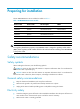
Preparing for installation The HP MSR3000 Router Series includes the models in Table 1.
• Do not open or close the chassis cover when the router is powered on. • Correctly connect the interface cables of the router. • Use an uninterrupted power supply (UPS). • If there are two power inputs, disconnect the two power inputs to power off the router. • Do not work alone when the router has power. • Always make sure the power has been disconnected during the installation and replacement procedures. Laser safety • Do not stare into any fiber port when the router has power.
Substance Concentration limit (particles/m3) NOTE: Dust particle diameter ≥ 5 μm The equipment room must also meet strict limits on salts, acids, and sulfides to eliminate corrosion and premature aging of components, as shown in Table 4. Table 4 Harmful gas limits in the equipment room Gas Max. (mg/m3) SO2 0.2 H2S 0.006 NH3 0.05 Cl2 0.
Figure 2 Airflow through the MSR3044/3064 chassis To ensure good ventilation, the following requirements must be met: • The air inlet and outlet vents are not blocked, and leave at least 10 cm (3.94 in) of clearance. • The installation site has a good cooling system. ESD prevention To prevent electrostatic discharge (ESD), follow these guidelines: • Make sure the router and the floor are well grounded. • Take dust-proof measures for the equipment room.
EMI All electromagnetic interference (EMI) sources, from outside or inside of the router and application system, adversely affect the router in a conduction pattern of capacitance coupling, inductance coupling, electromagnetic wave radiation, or common impedance (including grounding system) coupling. To prevent EMI, follow these guidelines: • Take measures against interference from the power grid.
Installation accessories Checklist before installation Table 5 Checklist before installation Item Requirements • There is a minimum clearance of 10 cm (3.94 in) Installation site Ventilation around the inlet and outlet vents for heat dissipation of the router chassis. • A good ventilation system is available at the installation site.
Item Requirements Temperature 0°C to 45°C (32°F to 113°F). Relative humidity 5% to 90% (noncondensing). Cleanness • Dust concentration ≤ 3 × 10⁴ particles/m3. • No visible dust on desk within three days. • The equipment and floor are well grounded. • The equipment room is dust-proof. • The humidity and temperature are at a proper level, respectively. • Wear an ESD wrist strap and uniform when ESD prevention touching a circuit board.
Item Requirements Tools • Installation accessories supplied with the router. • User supplied tools. Reference • Documents shipped with the router. • Online documents.
Installing the router WARNING! To avoid injury, do not touch bare wires, terminals, or parts with high-voltage hazard signs. IMPORTANT: • The barcode on the router chassis contains product information that must be provided to local sales agent before you return a faulty router for service. • Keep the tamper-proof seal on a mounting screw on the chassis cover intact, and if you want to open the chassis, contact HP for permission. Otherwise, HP shall not be liable for any consequence.
Figure 3 Installation flowchart Start Install an air filter Mount the router to a workbench Mount to a specific position? Mount the router to a rack Examine the workbench Mount the router to a rack Ground the router Install an interface module Connect interface cables Install a CF card Connect the router to a terminal Install a power supply Connect the power cord Verify the installation Troubleshoot the router Power on the router Operating correctly? Yes End 10 No Power off the router
Installing the router Installing an air filter No air filter is provided with the router. Purchase one yourself. Only the MSR3044 and MSR3064 support air filters. To install an air filter: 1. Face the left side (side of the inlet vents) of the router. 2. Install the upper and lower guide rails of the air filter to the chassis. See Figure 4. 3. Fasten the fastening screws on the guide rails with a Phillips screwdriver. Figure 4 Installing the upper and lower guide rails 4.
IMPORTANT: • Ensure good ventilation and 10 cm (3.94 in) of clearance around the chassis for heat dissipation. • Avoid placing heavy objects on the router. To mount the router on a workbench: 1. Make sure the workbench is clean, stable, and properly grounded. 2. Place the router upside down on the workbench and attach the rubber feet to the four round holes in the chassis bottom. Figure 6 Attaching the rubber feet 3. Place the router on the workbench with the upside up.
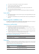
Figure 8 Front mounting brackets Figure 9 Rear mounting brackets Rack-mounting clearance requirements Figure 10 Rack-mounting clearances for the MSR3012/3024 60mm 483mm 65mm E1 cable RPS power cord Front mounting bracket 13
Figure 11 Rack-mounting clearances for the MSR3044/3064 Front mounting bracket Power cord E1 cable 480mm 60mm 60mm Table 6 Rack-mounting clearance requirements Model Router dimensions Rack clearance requirements The rack must meet all the following requirements: • Width—440 mm (17.32 in) • Height—44.2 mm (1.74 in) (1 RU) • Total depth—608 mm (23.94 in) 3012/3024 { { { 483 mm (19.02 in) for the chassis 65 mm (2.56 in) for connecting an RPS power cord at the front of the chassis 60 mm (2.
Model Router dimensions Rack clearance requirements The rack must meet all the following requirements: • Width—440 mm (17.32 in) • Height—88.2 mm (3.47 in) (2 RU) • Total depth—600 mm (23.62 in) 3044 { { { 480 mm (18.90 in) for the chassis 60 mm (2.36 in) for connecting an RPS power cord at the front of the chassis 60 mm (2.36 in) for connecting an E1 cable at the rear of the chassis • At least 80 mm (3.15 in) between the front rack post and the front door. • At least 550 mm (21.
Figure 12 Marking the positions of cage nuts for the front mounting brackets Figure 13 Marking the positions of cage nuts for the rear mounting brackets 16
3. Insert one edge of a cage nut into the hole. Use a flat-blade screwdriver to compress the other edge of the cage nut, and then push the cage nut fully into the hole. 4. Repeat step 3 to install other cage nuts to all the marked positions on the rack posts. Figure 14 Installing a cage nut 5. Attach the rear mounting brackets to the rack and fasten the screws. The depth of the router might be greater or smaller than the depth of the rack, depending on the rack model.
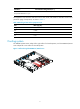
Figure 16 Attaching the rear mounting brackets (router depth smaller than rack depth) 6. Attach the front mounting brackets to the chassis and fasten the screws. 7. Attach load-bearing screws to the rear of the chassis.
Figure 19 Attaching the front mounting brackets and load-bearing screws to the MSR3064 8. Place the router on the rack, making sure the load-bearing screws hang on the rear mounting brackets. Secure the chassis in the rack by attaching the front mounting brackets with proper pan head screws onto the back.
Figure 20 Mounting the router to the rack Grounding the router WARNING! Correctly connecting the router grounding cable is crucial to lightning protection and EMI protection. IMPORTANT: The resistance reading should be smaller than 5 ohms between the chassis and the ground. Grounding the router through the grounding terminal on the rack IMPORTANT: Make sure the rack is properly grounded before grounding the router.
To connect the grounding cable: 1. Remove the two grounding screws from the rear panel of the chassis. 2. Attach the grounding screw to the ring terminal of the grounding cable. See Figure 21. 3. Use a Phillips screwdriver to fasten the grounding screw into the grounding screw hole. 4. Remove the grounding screw from the grounding point on the rack. 5. Use a needle-nose pliers to bend a hook at the other end of the grounding cable, attach it to the grounding point, and secure it with a screw.
Figure 22 Grounding the router through the grounding terminal on the rack 22
1 2 Grounding the router with a grounding strip If a grounding strip is available at the installation site, connect the grounding cable to the grounding strip. Follow the same procedures in "Grounding the router through the grounding terminal on the rack" to connect the grounding cable.
Figure 23 Grounding the router with a grounding strip 1 2 Grounding the router with a grounding conductor buried in the earth ground If the installation site has no grounding strips, but earth ground is available, hammer a 0.5 m (1.64 ft) or longer angle iron or steel tube into the earth ground to serve as a grounding conductor. The steel tube must be zinc-coated. Weld the yellow-green grounding cable to the angel iron or steel tube and treat the joint for corrosion protection.
Figure 24 Removing the filler panel Figure 25 Installing the SIC Installing a DSIC CAUTION: DSIC interface modules are not hot swappable. Make sure the router is powered off before installing a DSIC. To install a DSIC: 1. Remove the screws on the filler panel on a SIC slot of an MSR3024, MSR3044, or MSR3064 to remove the filler panel. For an MSR3024, MSR3044, or MSR3064, a DSIC can be installed after you remove the slot divider between slot 1 and slot 2, or between slot 3 and slot 4. 2.
Figure 26 Removing the filler panel Figure 27 Removing the slot divider 3. Insert the DSIC into the slot and push it along the slide rails until it makes close contact with the backplane of the router. Figure 28 Installing a DSIC 4. Fasten the captive screws to secure the DSIC.
IMPORTANT: • You can install an HMIM when the router is powered on. However, before replacing an HMIM when the router is powered on, you must execute the remove hmimslot slotnumber command. • An HMIM interface module can be 1U or 0.5U. This section takes a 0.5U interface module for example. When you install a 1U interface module to an MSR router, remove the filler panels of the target slot and the neighboring slot above.
IMPORTANT: • To install a MIM, install it to the HMIM adapter and then insert it into the HMIM slot. • You can install a MIM when the router is powered on. However, before replacing a MIM when the router is powered on, you must execute the remove hmimslot slotnumber command. • A MIM interface module can be 1U or 0.5U. This section takes a 0.5U interface module for example.
Connecting the router to the network Connect the router to the network before powering on the router. This section describes how to connect the router to the network through Ethernet cables. Connecting an Ethernet cable 1. Plug one end of an Ethernet twisted pair cable into the copper Ethernet port (RJ-45 port) to be connected on the router. 2. Plug the other end of the cable into the RJ-45 port of the peer device.
connector at one end of another fiber cable into the Tx port of the router and the LC connector at the other end to the Rx port of the peer device. 5. Examine the Ethernet port LED after connection. For more information, see "Appendix B LEDs." Figure 34 Connecting an optical fiber Installing a CF card 1. Open the CF card cover by pressing the spring clip. 2. Push the CF card eject button all the way into the slot, and make sure the button does not project from the panel. 3.
Logging in through the console port Connecting a console cable You can log in only through the console port by using a console or USB console cable the first time you log in to your router. IMPORTANT: When you connect a PC to a powered-on router, connect the RJ-45 connector to the router after connecting the DB-9 connector of the console cable to the PC. To connect a console cable: 1. Plug the DB-9 female connector to the serial port of the configuration terminal. 2.
Figure 37 Connecting the USB cable 5. Click the following link, or copy it to the address bar on the browser to log in to download page of the USB console driver, and download the driver. http://www.exar.com/connectivity/uart-and-bridging-solutions/usb-uarts/xr21v1410 6. Select a driver program according to the operating system you use: { { 7. XR21V1410_XR21B1411_Windows_Ver1840_x86_Installer.EXE—Applicable to 32-bit operating systems. XR21V1410_XR21B1411_Windows_Ver1840_x64_Installer.
Figure 39 Software installation 9. Click Finish. Figure 40 Completing the device driver installation wizard Setting terminal parameters This section uses a PC with Windows XP as an example.
1. Select Start > All Programs > Accessories > Communications > HyperTerminal. The Connection Description dialog box appears. Figure 41 Connection description 2. Select the serial port to be used from the Connect using list, and click OK. Figure 42 Setting the serial port used by the HyperTerminal connection 3. Set Bits per second to 9600, Data bits to 8, Parity to None, Stop bits to 1, and Flow control to None, and click OK.
Figure 43 Setting the serial port parameters 4. Select File > Properties in the HyperTerminal window. Figure 44 HyperTerminal window 5. On the Settings tab, set the emulation to VT100 or Auto detect and click OK.
Figure 45 Setting terminal emulation in test Properties dialog box Installing a power supply IMPORTANT: • Only the MSR3044 and MSR3064 support power supplies. • To install multiple power supplies, make sure all power supplies are AC input or DC input. Installing an AC/DC power supply 1. Face the front of the router and locate the slot to be used. 2. Loosen the captive screws with a Phillips screwdriver to remove the filler panel from the slot. Keep the removed filler panel for future use.
Figure 46 Installing an AC power supply Figure 47 Installing a DC power supply Installing a PoE power supply 1. Face the front of the router and locate the slot to be used. 2. Loosen the captive screws with a Phillips screwdriver to remove the filler panel from the slot. Keep the removed filler panel for future use. Skip this step if you install the power supply to the PWR1 slot. 3.
Figure 48 Installing a PoE power supply Connecting the power cord The power cords in the figures of this section are only for illustration. Connecting an AC power cord 1. Make sure the router is well grounded, and the power switch on the router is in the OFF position. 2. Connect one end of the AC power cord to the AC receptacle on the router, and use a cable tie to secure the power cord. 3. Connect the other end of the power cord to the AC power source.
Figure 50 Connecting an AC power cord to an MSR3044/3064 router Connecting a DC power cord WARNING! Pay attention to the mark on a power cord to avoid connection errors. The MSR3012/3024 and MSR3044/3064 use different DC connectors, but the power cord connection procedures are the same. To connect DC power cords: 1. Make sure the router is well grounded, and the power switch on the router is in the OFF position. 2.
Figure 51 Connecting a DC power cord for an MSR3012/3024 2 1 Figure 52 Connecting a DC power cord for an MSR3044/3064 2 1 Connecting an RPS power cord The MSR3012 and MSR3024 offer remote power supply (RPS) support. As an external power supply, RPS can provide power supply for the device in case of power supply abnormality. It enhances the reliability of the device. The router has a sticky label and a protective cover when shipped to protect the RPS receptacle. To connect an RPS power cord: 1.
Figure 53 Removing the sticky label and protective cover 3. Insert one end of the RPS power cord to the RPS receptacle on the router and fasten the screws on the RPS power cord plug. 4. Make sure the RPS power is OFF and connect the other end of the power cord to the RPS power source. Figure 54 Connecting the RPS power cord Verifying the installation After you complete the installation, verify that: • There is enough space for heat dissipation around the router, and the rack or workbench is stable.
• The console cable is properly connected, the terminal or PC used for configuration has started, and the configuration parameters have been set. • If a CF card is used, verify that the CF card is in position. • Make sure the installed HMIMs/MIMs are in position. Powering on the router 1. Turn on the switch of the power supply system for the router. 2. Turn on the switch of the AC or DC power supplies.
..........Done. System image is starting... Line aux0 is available. Press ENTER to get started. Press Enter, and the following prompt appears: You can now configure the router. Examining the router after power-on After the router is powered on, verify that: The LEDs on the front panel are operating correctly: • LED Status Description PWR Steady green The power supply is supplying power correctly. SYS Slow flashing green The router is operating correctly.
Replacement procedure IMPORTANT: • The barcode on the router chassis contains product information that must be provided to local sales agent before you return a faulty router for service. • Keep the tamper-proof seal on a mounting screw on the chassis cover intact, and if you want to open the chassis, contact HP for permission. Otherwise, HP shall not be liable for any consequence. Replacing a power supply Power supplies are hot swappable.
WARNING! • To avoid bodily injury and equipment damage, make sure all power supplies connected to the router are powered off, all power cords and interface cables are removed before you maintain the hardware. • Wear an ESD-preventive wrist and make sure it makes good skin contact and is well grounded. • After you maintain the hardware, reinstall the chassis cover. Removing the chassis cover from the MSR3012/MSR3024 1. Place the router on a flat ground and have the rear panel face you. 2.
Figure 58 Lifting the chassis cover Removing the chassis cover from the MSR3044/MSR3064 1. Place the router on a flat ground. 2. Use a Phillips screwdriver to remove the fastening screws at the top of the router from chassis cover. 3. Lift the chassis cover and put it away.
Locating internal modules Figure 61 MSR3012 internal module locations (1) Front panel (2) Rear panel 47 (3) VPM
Figure 62 MSR3024 internal module locations (1) Front panel (2) Rear panel (4) Memory module 48 (3) VPM
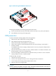
Figure 63 MSR3044 internal module locations 1 2 (1) Front panel 4 3 (2) Rear panel (4) Memory module 49 (3) VPMs
Figure 64 MSR3064 internal module locations 1 2 (1) Front panel 4 3 (2) Rear panel (3) VPMs (4) Memory module Replacing a VPM VPM (Voice Processing Module) functions to implement the encryption/decryption, EC and CNG of voices.
Figure 65 VPM To replace a VPM: 1. Pull the release latches away from the VPM at both ends so that the VPM springs up from the slot. 2. Holding the non-conductive edge, remove the VPM. Keep the removed VPM for future use. 3. Align the polarization notch of a new VPM with the VPM slot on the main board and insert it into the slot along the slide rails. 4. Carefully and firmly press the VPM at both ends until you hear a click. This indicates the VPM is seated in the slot. 5.
1. Pull the release latches away from the memory module at both ends so that the memory module springs up from the slot. 2. Holding the non-conductive edge, remove the memory module. Keep the removed memory module for future use. 3. Align the polarization notch of a new memory module with the memory module slot on the main board and insert the memory module into the slot along the slide rails. 4. Carefully and firmly press the memory module at both ends until you hear a click.
To install new slide rails, see "Installing the router." Figure 71 Removing slide rails Replacing a CF card CAUTION: Execute the umount cfb0: command before you remove the CF card if the router is powered on. To replace a CF card: 1. Press down the spring clip of the CF card cover and open the cover. 2. Press the CF card eject button of the CF card reader so that the eject button projects from the panel. 3.
Replacing a SIC CAUTION: SIC interface modules are not hot swappable. Make sure the router is powered off before installing a SIC. 1. Completely loosen the captive screws of the SIC. 2. Gently pull the SIC out along the slide rails. 3. Install a new SIC. For the installation procedure, see "Installing the router." If you do not install a SIC, install a filler panel and tighten the screws.
2. Gently pull the DSIC out along the slide rails. If you need to install SIC or DSIC interface modules, see "Installing the router" for the installation procedure. To install filler panels, proceed to steps 3 and 4. 3. Gently push the slot divider into the DSIC slot along the slide rails and tighten the screws. 4. Install filler panels and tighten the screws.
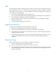
Figure 77 Installing filler panels Replacing an HMIM WARNING! You can replace an HMIM when the router is powered on. However, before replacing an HMIM when the router is powered on, you must execute the remove hmimslot slotnumber command. 1. Completely loosen the captive screws of the HMIM. 2. Gently pull the HMIM out of the slot along the slide rails. 3. Install a new HMIM. For the installation procedure, see "Installing the router.
Figure 79 Installing a filler panel Replacing a MIM WARNING! You can replace a MIM when the router is powered on. However, before replacing a MIM when the router is powered on, you must execute the remove hmimslot slotnumber command. To replace a MIM: 1. Completely loosen the captive screws of the HMIM adapter. 2. Gently pull the MIM and the HMIM adapter out of the slot along the slide rails. Figure 80 Removing a MIM and the HMIM adapter 3.
Figure 81 Removing a MIM Figure 82 Installing a filler panel 58
Troubleshooting IMPORTANT: • The barcode on the router chassis contains product information that must be provided to local sales agent before you return a faulty router for service. • Keep the tamper-proof seal on a mounting screw on the chassis cover intact, and if you want to open the chassis, contact HP for permission. Otherwise, HP shall not be liable for any consequence. Troubleshooting the power supply system failure Symptom The router cannot be powered on. The power LED is off. Solution 1.
Troubleshooting the configuration system failures If the router operates properly after being powered on, the boot information is displayed on the configuration terminal. If the configuration system is faulty, the configuration terminal displays garbled characters or does not display anything. No display on the configuration terminal Symptom After the router is powered on, the console terminal does not display anything.
Solution 1.
Solution 1. Verify that the interface module makes good contact with the rear panel of the router slot. 2. Verify that the router supports the interface module. 3. Verify that the interface module is installed in the specified router slot. 4. Verify that a correct cable is used. 5. Verify that the cable is correctly connected.
Appendix A Chassis views and technical specifications Chassis views The following figures are for illustration only.
MSR3012 DC Figure 85 MSR3012 DC front view 1 2 11 10 3 4 5 7 6 8 9 (1) Gigabit Ethernet port (GE1) (2) Gigabit Ethernet port (GE2) (3) USB console port (CON) (4) USB port 1 (5) SFP interface (SFP0) (6) RPS receptacle cover (7) Power switch (8) DC-input power receptacle (9) USB port 0 (10) Console port/AUX port (CON/AUX) (11) Gigabit Ethernet port (GE0) Figure 86 MSR3012 DC rear view (1) Grounding terminal (2) SIC slot (slot 2) (3) SIC slot (slot 1) (2) USB port 0 (3) USB port 1 (4
(4) RPS receptacle cover (5) Power switch (6) AC-input power receptacle (7) Power cord bail latch (8) SFP port (SFP0) (9) USB console port (CON) (10) Console port/AUX port (CON/AUX) (11) Gigabit Ethernet port (GE2) (12) Gigabit Ethernet port (GE1) (13) Gigabit Ethernet port (GE0) Figure 88 MSR3024 AC rear view (1) Grounding terminal (2) SIC slot (slot 4) (3) SIC slot (slot 3) (4) HMIM slot (slot 6) (5) HMIM slot (slot 5) (6) SIC slot (slot 1) (7) SIC slot (slot 2) MSR3024 DC Figure 89 MSR3
Figure 90 MSR3024 DC rear view (1) Grounding terminal (2)SIC slot (slot 4) (3) SIC slot (slot 3) (4) HMIM slot (slot 6) (5) HMIM slot (slot 5) (6) SIC slot (slot 1) (7) SIC slot (slot 2) MSR3024 PoE Figure 91 MSR3024 PoE front view (1) CF card cover (2) USB port 0 (3) USB port 1 (4) RPS receptacle cover (5) Power switch (6) AC-input power receptacle (7) Power cord bail latch (8) SFP port (SFP0) (9) USB console port (CON) (10) Console port/AUX port (CON/AUX) (11) Gigabit Ethernet port (GE2
MSR3044 Figure 93 MSR3044 front view (1) SIC slot (slot 4) (2) SIC slot (slot 3) (3) SIC slot (slot 2) (4) USB port 0 (5) USB port 1 (6) SIC slot (slot 1) (7) Gigabit Ethernet port (GE1) (8) Gigabit Ethernet port (GE2) (9) USB console port (CON) (10) Console port/AUX port (CON/AUX) (11) Gigabit Ethernet port (GE0) (12) SFP port (SFP1) (13) SFP port (SFP0) (14) HMIM slot (slot 5) (15) HMIM slot (slot 7) (16) CF card cover (17) HMIM slot (slot 8) (18) HMIM slot (slot 6) (2) Power supply slo
MSR3064 Figure 95 MSR3064 front view (1) SIC slot (slot 4) (2)SIC slot (slot 3) (3) SIC slot (slot 2) (4) USB port 0 (5) USB port 1 (6) SIC slot (slot 1) (7) Gigabit Ethernet port (GE1) (8) Gigabit Ethernet port (GE2) (9) USB console port (CON) (10) HMIM slot (slot 5) (11) HMIM slot (slot 7) (12) HMIM slot (slot 9) (13) Console port/AUX port (CON/AUX) (14) Gigabit Ethernet port (GE0) (15) SFP port (SFP1) (16) SFP port (SFP0) (17) CF card cover (18) HMIM slot (slot 6) (19) HMIM slot (slot
AC power supply Figure 97 AC power supply (1) Captive screw (2) Power switch (3) Air outlet vent (4) Power receptacle DC power supply Figure 98 DC power supply (1) Captive screw (2) Power switch (3) Air outlet vent (4) Power receptacle 69
PoE power supply Figure 99 PoE power supply (1) Captive screw (2) Power switch (3) Air outlet vent (4) Power receptacle Technical specifications Table 7 Technical specifications Item 3012 3024 CON/AUX ports 1 USB console ports 1 USB ports 2 Gigabit Ethernet ports 3 SIC/DSIC slots 2 SIC slots 4 SIC slots/2 DSIC slots HMIM slots 1 VPM slots N/A 3044 3064 2 4 6 1 2 2 88.1 × 440 × 480 mm (3.47 × 17.32 × 18.90 in) 130.5 × 440 × 480 mm (5.14 × 17.32 × 18.
Item 3012 3024 3044 3064 Rated power for AC/DC power supply 125 W 125 W AC: 300 W AC: 300 W Rated power for PoE power supply Not supported 275 W 750 W 750 W Rated power for each PoE port 15.
Appendix B LEDs Panel LEDs MSR3012 Figure 100 MSR3012 LEDs (1) Console port LED (2) USB console port LED (3) SFP port LED (SFP0) (4) Gigabit Ethernet port LED (GE0) (5) Gigabit Ethernet port LED (GE1) (6) Gigabit Ethernet port LED (GE2) (7) System LED (SYS) (8) Power supply LED (PWR) MSR3024 Figure 101 MSR3024 LEDs (1) Console port LED (2) USB console port LED (3) SFP port LED(SFP0) (4) Gigabit Ethernet port LED (GE0) (5) Gigabit Ethernet port LED (GE1) (6) Gigabit Ethernet port LED (GE2) (7
MSR3044 Figure 102 MSR3044 LEDs (1) CF card LED (2) System LED (SYS) (3) Power supply LED (PWR) (4) PoE power supply LED (5) VPM (slot 0) LED (VPM0) (6) VPM (slot 1) LED (VPM1) (7) Gigabit Ethernet port LED (GE0) (8) SFP port LED (SFP0) (9) Gigabit Ethernet port LED (GE1) (10) SFP port LED (SFP1) (11) Gigabit Ethernet port LED (GE2) (12) Console port LED (1)CF card LED (2) System LED (SYS) (3) Power supply LED (PWR) (4) PoE power supply LED (5) VPM (slot 0) LED (VPM0) (6) VPM (slot 1) LED
Power supply LEDs Appearance Figure 104 AC power supply LEDs (1) Power input LED (2) Power output LED Figure 105 DC power supply LEDs 1 (1) Power input LED 2 (2) Power output LED Figure 106 PoE power supply LEDs (1) Power input LED (2) Power output LED 74
LED description LEDs State Description Flashing green (8 Hz) The BootWare runs. Steady green The SDRAM is performing self-test. Flashing green (1 Hz) Comware has started with the configuration file and the router has booted up. Flashing yellow (1 Hz) The DDR3 SDRAM has failed the self-test. Flashing yellow (8 Hz) The extended segment does not exist. Steady yellow The boot image does not exist. Off No power input, or exceptions have occurred.
LEDs AC OK DC OK Input Output AC OK DC OK State Description Off No link is present on the SFP interface. Off No power input or the power input is faulty. Steady green The power is input properly. Off No power output or the power output is faulty. Steady green The power is output properly. Off No power input or the power input is faulty. Steady green The power is input properly. Off No power output or the power output is faulty. Steady green The power is output properly.
Appendix C Slot arrangement Each of the MSR3000 routers provides slots for SIC and HMIM interface cards. On the MSR3024, MSR3044, and MSR3064, you can combine two SIC slots into one DSIC slot by removing the slot divider. The fixed ports on the MSR3000 panel are located in slot 0.
Support and other resources Contacting HP For worldwide technical support information, see the HP support website: http://www.hp.
Conventions This section describes the conventions used in this documentation set. Command conventions Convention Description Boldface Bold text represents commands and keywords that you enter literally as shown. Italic Italic text represents arguments that you replace with actual values. [] Square brackets enclose syntax choices (keywords or arguments) that are optional. { x | y | ... } Braces enclose a set of required syntax choices separated by vertical bars, from which you select one.
Network topology icons Represents a generic network device, such as a router, switch, or firewall. Represents a routing-capable device, such as a router or Layer 3 switch. Represents a generic switch, such as a Layer 2 or Layer 3 switch, or a router that supports Layer 2 forwarding and other Layer 2 features. Represents an access controller, a unified wired-WLAN module, or the switching engine on a unified wired-WLAN switch. Represents an access point. Represents a mesh access point.
Index ACDEGILMNPRSTVW A Installing the router in a rack,12 AC power supply,69 L Appearance,74 Laser safety,2 Lightning protection,5 C Locating internal modules,47 Cleanness,2 Connecting a console cable,31 M Connecting a DC power cord,39 Mounting the router on a workbench,11 Connecting an AC power cord,38 MSR3012,72 Connecting an Ethernet cable,29 MSR3012 AC,63 Connecting an optical fiber,29 MSR3012 DC,64 Connecting an RPS power cord,40 MSR3024,72 Cooling system,3 MSR3024 AC,64 D MSR30
V W Verifying before power-on,41 Websites,78 82