
R0106-HP MSR Router Series Fundamentals Command Reference(V7)

215
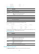
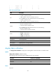
6 HMIM-4GEE Normal 4
7 HMIM-1CE3 Normal 1
8 HMIM-2SAE Normal 2
Table 31 Command output
Field Descri
p
tion
Slot No. Slot number of the card.
Board Type Hardware type of the card.
Status
Card status:
• Fault—The card is faulty and cannot start up.
• Normal—The card is operating correctly.
Max Ports Maximum number of ports that the card supports.
Type Card type.
Hardware Hardware version of the card.
Driver Driver version of the card.
CPLD CPLD version of the card.
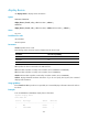
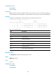
# On an MSR4000, display device information on the default context.
<Sysname> display device
Slot No. Board Type Status Primary SubSlots
-----------------------------------------------------------------------------
0 MPU-100 Normal Master 0
1 MPU-100 Normal Standby 0
2 SPU-200 Normal N/A 10
The output shows that the MSR4000 has two MPUs and one interface card. The standby MPU is in slot
0, the active MPU is in slot 1, and the interface card is in slot 2.
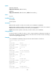
Table 32 Command output
Field Descri
p
tion
Slot No. Slot number of the card.
Board Type Hardware type of the card.
Status
Card status:
• Absent—The slot is not installed with a card.
• Fault—The card is faulty and cannot start up.
• Normal—The card is operating correctly.
Primary
MPU status:
• Standby—The card is the standby MPU.
• Master—The card is the active MPU.
SubSlots Maximum number of subcards that the card supports.
display device manuinfo
Use display device manuinfo to display the electronic label information of the device.