HP MSR Router Series Fundamentals Configuration Guide(V7) Part number: 5998-5673 Software version: CMW710-R0106 Document version: 6PW100-20140607
Legal and notice information © Copyright 2014 Hewlett-Packard Development Company, L.P. No part of this documentation may be reproduced or transmitted in any form or by any means without prior written consent of Hewlett-Packard Development Company, L.P. The information contained herein is subject to change without notice.
Contents Using the CLI ································································································································································ 1 CLI views ············································································································································································ 1 Entering system view from user view ·········································································································
RBAC configuration examples ······································································································································ 26 RBAC configuration example for local AAA authentication users ··································································· 26 RBAC configuration example for RADIUS authentication users ······································································· 28 RBAC configuration example for HWTACACS authentication users ··················
Using the device as an FTP server ································································································································ 79 Configuring basic parameters ····························································································································· 80 Configuring authentication and authorization ··································································································· 80 Manually releasing FTP connections ·····
Configuration file content organization and format ························································································ 103 FIPS compliance ··························································································································································· 104 Enabling configuration encryption ····························································································································· 104 Saving the running configura
Automatic-configuration parameter acquisition process ················································································· 131 Configuration file acquisition process ··············································································································· 131 Deploying and configuring servers for server-based automatic configuration ······················································ 133 DHCP server configuration guidelines ··············································
Index ········································································································································································ 162 vi
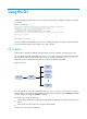
Using the CLI At the command-line interface (CLI), you can enter text commands to configure, manage, and monitor your device. Figure 1 CLI example You can use different methods to log in to the CLI, including through the console port, Telnet, and SSH. For more information about login methods, see "Login overview." CLI views Commands are grouped in different views by function. To use a command, you must enter its view. CLI views are hierarchically organized, as shown in Figure 2.
• Configure global settings (such as the daylight saving time, banners, and hotkeys) and some functions. • Enter different function views. For example, you can perform the following tasks: { Enter interface view to configure interface parameters. { Enter VLAN view to add ports to the VLAN. { Enter user line view to configure login user attributes. A function view might have child views. For example, BGP view has child views IPv4 unicast instance view and BGP-VPN IPv4 unicast instance view.
• Enter a space and a question mark after a command keyword to display all available, subsequent keywords and arguments. { If the question mark is in the place of a keyword, the CLI displays all possible keywords, each with a brief description. For example: terminal ? { logging Display logs on the current terminal monitor Enable to display logs on the current terminal If the question mark is in the place of an argument, the CLI displays the description of the argument.
Editing a command line To edit a command line, use the keys listed in Table 1 or the hotkeys listed in Table 2. When you are finished, you can press Enter to execute the command. Table 1 Command line editing keys Keys Function Common keys If the edit buffer is not full, pressing a common key inserts a character at the cursor and moves the cursor to the right. The edit buffer can store up to 511 characters.
Configuring and using command keyword aliases The command keyword alias function allows you to use your own keywords to replace the following keywords when you execute a command: • The first keywords of non-undo commands. • The second keywords of undo commands. For example, if you configure show as the alias for the display keyword, you can enter either show clock or display clock to execute the display clock command.
Step Command Remarks By default: • Ctrl+G is assigned the display current-configuration command. 2. Assign a command to a hotkey. hotkey { ctrl_g | ctrl_l | ctrl_o | ctrl_t | ctrl_u } command • Ctrl+L is assigned the display ip routing-table command. • Ctrl+O is assigned the undo debugging all command. • No command is assigned to Ctrl+T or Ctrl+U. 3. (Optional.) Display hotkeys. Available in any view.
Enabling redisplaying entered-but-not-submitted commands Your input might be interrupted by system information output. If redisplaying entered-but-not-submitted commands is enabled, the system redisplays your input after finishing the output. You can then continue entering the command line. To enable redisplaying entered-but-not-submitted commands: Step Command Remarks 1. Enter system view. system-view N/A 2. Enable redisplaying entered-but-not-submitt ed commands.
Table 4 Comparison between the two types of command history buffers Item Command history buffer for a user line Command history buffer for all user lines What kind of commands are stored in the buffer? Commands successfully executed by the current user of the user line. Commands successfully executed by all login users. Cleared when the user logs out? Yes. No. How to view buffered commands? Use the display history-command command. Use the display history-command all command. 3.
By default, up to 24 lines can be displayed on a screen. You can change the limit by using the screen-length screen-length command. For more information about this command, see Fundamentals Command Reference. You can also disable pausing between screens of output for the current session. Then, all output is displayed at one time and the screen is refreshed continuously until the final screen is displayed. Output controlling keys Keys Function Space Displays the next screen.
5: Subnet mask: 255.255.255.0 6: Description: For LAN Access 7: Name: VLAN 0999 8: Tagged ports: 9: Untagged ports: 10: None GigabitEthernet2/1/0 Filtering the output from a display command You can use the | { begin | exclude | include } regular-expression option to filter the display command output: • begin—Displays the first line matching the specified regular expression and all subsequent lines. • exclude—Displays all lines not matching the specified regular expression.
Characters [] Meaning Examples Matches a single character in the brackets. "[16A]" matches a string containing 1, 6, or A; "[1-36A]" matches a string containing 1, 2, 3, 6, or A (- is a hyphen). To match the character "]", put it immediately after "[", for example, []abc]. There is no such limit on "[". [^] Matches a single character that is not in the brackets. "[^16A]" matches a string that contains one or more characters except for 1, 6, or A, such as "abc".
# Use | begin line in the display current-configuration command to match the first line of output that contains line to the last line of output.
# role name level-9 description Predefined level-9 role # role name level-10 description Predefined level-10 role # role name level-11 description Predefined level-11 role # role name level-12 description Predefined level-12 role # role name level-13 description Predefined level-13 role # role name level-14 description Predefined level-14 role # user-group system # return # Use | exclude Direct in the display ip routing-table command to filter out direct routes and display only the non-direct routes.
• Append the output to the end of a file. Use this method if you want to use one file for multiple display commands. To save the output from a display command to a file, use one of the following commands in any view: Task Command Save the output from a display command to a separate file. display command > filename Append the output from a display command to the end of a file. display command >> filename For example: # Save the VLAN 1 settings to a separate file named vlan.txt.
Viewing and managing the output from a display command effectively You can use the following measures in combination to filter and manage the output from a display command: • Numbering each output line from a display command • Filtering the output from a display command • Saving the output from a display command to a file To use multiple measures to view and manage the output from a display command effectively, execute the following command in any view: Task Command View and manage the output from a
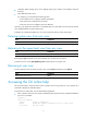
Configuring RBAC Overview Role based access control (RBAC) controls user access to items and system resources based on user role. Items include commands and XML elements. System resources include interfaces, VLANs, and VPN instances. On devices that support multiple users, RBAC is used to assign access permissions to user roles that are created for different job functions. Users are given permission to access a set of items and resources based on the users' user roles.
A user role can access the set of permitted commands and XML elements specified in the user role rules. The user role rules include predefined (identified by sys-n) and user-defined user role rules. For more information about the user role rule priority, see "Configuring user role rules." Resource access policies Resource access policies control access of user roles to system resources and include the following types: • Interface policy—Controls access to interfaces.
User role name Permissions • level-0—Has access to diagnostic commands, including ping, tracert, ssh2, telnet, and super. Level-0 access rights are configurable. • level-1—Has access to the display commands of all features and resources in the system except display history-command all. The level-1 user role also has all access rights of the level-0 user role. Level-1 access rights are configurable. • level-2 to level-8, and level-10 to level-14—Do not have any access rights by default.
FIPS compliance The device supports the FIPS mode that complies with NIST FIPS 140-2 requirements. Support for features, commands, and parameters might differ in FIPS mode and non-FIPS mode. For more information about FIPS mode, see Security Configuration Guide. Configuration task list Tasks at a glance (Required.) Creating user roles (Required.) Configuring user role rules (Optional.) Configuring feature groups (Optional.) Changing resource access policies (Optional.) Assigning user roles (Optional.
Configuration restrictions and guidelines When you configure RBAC user role rules, follow these restrictions and guidelines: • You can configure up to 256 user-defined rules for a user role. The total number of user-defined user role rules cannot exceed 1024. • Any rule modification, addition, or removal for a user role takes effect only on users who are logged in with the user role after the change. • If two user-defined rules of the same type conflict, the rule with the higher ID takes effect.
Step Command Remarks 1. Enter system view. system-view N/A 2. Create a feature group and enter feature group view. role feature-group name feature-group-name By default, the system has the following predefined feature groups: • L2—Includes all Layer 2 commands. • L3—Includes all Layer 3 commands. These two groups are not user configurable. By default, a feature group does not have any features. 3. Add a feature to the feature group.
Step 3. Enter user role VLAN policy view. 4. (Optional.) Specify a list of VLANs accessible to the user role. Command Remarks vlan policy deny permit vlan vlan-id-list By default, the VLAN policies of user roles permit access to all VLANs. This command disables the access of the user role to any VLAN. By default, no accessible VLANs are configured. To add more accessible VLANs, repeat this step. Changing the VPN instance policy of a user role Step Command Remarks 1. Enter system view.
Step 2. Enable the default user role function. Command Remarks By default, the default user role function is disabled. role default-role enable If the none authorization method is used for local users, you must enable the default user role function. Assigning user roles to remote AAA authentication users For remote AAA authentication users, user roles are configured on the remote authentication server. For information about configuring user roles for RADIUS users, see the RADIUS server documentation.
Step Command Remarks • Enter user line view: 2. Enter user line view or user line class view. line { first-num1 [ last-num1 ] | { aux | console | tty | vty } first-num2 [ last-num2 ] } • Enter user line class view: line class { aux | console | tty | vty } For information about the priority order and application scope of the configurations in user line view and user line class view, see "Logging into the CLI." Repeat this step to specify up to 64 user roles on a user line. 3.
Table 7 User role authentication modes Keywords local Authentication mode Local password authentication only (local-only) Description The device uses the locally configured password for authentication. If no local password is configured for a user role in this mode, an AUX or console user can obtain the user role authorization by either entering a string or not entering anything. The device sends the username and password to the HWTACACS or RADIUS server for remote authentication.
Obtaining temporary user role authorization AUX, VTY, or TTY users must pass authentication before they can use a user role that is not included in the user account they are logged in with. Perform the following task in user view: Task Obtain the temporary authorization to use a user role. Command Remarks The operation fails after three consecutive unsuccessful password attempts.
Configuration procedure # Assign an IP address to GigabitEthernet 2/1/1, the interface connected to the Telnet user. system-view [Router] interface gigabitethernet 2/1/1 [Router-GigabitEthernet2/1/1] ip address 192.168.1.70 255.255.255.0 [Router-GigabitEthernet2/1/1] quit # Enable Telnet server. [Router] telnet server enable # Enable scheme authentication on the user lines for Telnet users.
Verifying the configuration # Telnet to the router, and enter the username and password to access the router. (Details not shown.) # Verify that you cannot enter any interface view except the views of GigabitEthernet 2/1/2 to GigabitEthernet 2/1/4. This example uses GigabitEthernet 2/1/1. system-view [Router] interface gigabitethernet 2/1/1 Permission denied. # Verify that you can access GigabitEthernet 2/1/2 to GigabitEthernet 2/1/4 to configure them. This example uses GigabitEthernet 2/1/2.
Figure 4 Network diagram Configuration procedure Make sure the settings on the router and the RADIUS server match. 1. Configure the router: # Assign an IP address to GigabitEthernet 2/1/1, the interface connected to the Telnet user. system-view [Router] interface gigabitethernet 2/1/1 [Router-GigabitEthernet2/1/1] ip address 192.168.1.70 255.255.255.0 [Router-GigabitEthernet2/1/1] quit # Assign an IP address to GigabitEthernet 2/1/2, the interface connected to the FreeRADIUS server.
[Router] domain bbb [Router-isp-bbb] authentication login radius-scheme rad [Router-isp-bbb] authorization login radius-scheme rad [Router-isp-bbb] quit # Create the feature group fgroup1. [Router] role feature-group name fgroup1 # Add the features arp and radius to the feature group. [Router-featuregrp-fgroup1] feature arp [Router-featuregrp-fgroup1] feature radius [Router-featuregrp-fgroup1] quit # Create the user role role2.
[Router] domain abc [Router-isp-abc] authentication login radius-scheme abc [Router-isp-abc] quit # Verify that you can use all read and write commands of the features radius and arp. This example uses radius. [Router] radius scheme rad [Router-radius-rad] primary authentication 2.2.2.2 [Router-radius-rad] display radius scheme rad … Output of the RADIUS scheme is omitted. # Verify that you cannot configure any VLAN except VLANs 1 to 20. This example uses VLAN 10 and VLAN 30.
Configuration procedure 1. Configure the router: # Assign an IP address to GigabitEthernet 2/1/1, the interface connected to the Telnet user. system-view [Router] interface gigabitethernet 2/1/1 [Router-GigabitEthernet2/1/1] ip address 192.168.1.70 255.255.255.0 [Router-GigabitEthernet2/1/1] quit # Assign an IP address to GigabitEthernet 2/1/2, the interface connected to the RADIUS server. [Router] interface gigabitethernet 2/1/2 [Router-GigabitEthernet2/1/2] ip address 10.1.1.2 255.255.255.
# Delete the default user role network-operator. [Router-luser-manage-test] undo authorization-attribute user-role network-operator [Router-luser-manage-test] quit # Set the local authentication password to 654321 for the user role level-3. [Router] super password role level-3 simple 654321 [Router] quit 2. Configure the HWTACACS server: This example uses ACSv4.0. a. Add a user account test. (Details not shown.) b. Access the Advanced TACACS+ Settings page. c.
Press CTRL+K to abort Connected to 192.168.1.59 ... ****************************************************************************** * Copyright (c) 2004-2014 Hewlett-Packard Development Company, L.P. * * Without the owner's prior written consent, * * no decompiling or reverse-engineering shall be allowed.
Analysis The local user might have been assigned to user roles without your knowledge. For example, the local user is automatically assigned a default user role when you create the user. Solution To resolve the problem: 1. Use the display local-user command to examine the local user accounts for undesirable user roles, and delete them. 2. If the problem persists, contact HP Support.
Login overview The first time you access the device, you can only log in to the CLI through the console port. After login, you can change console login parameters or configure other access methods, including AUX, Telnet, SSH, modem, and SNMP. The device supports the FIPS mode that complies with NIST FIPS 140-2 requirements. Support for features, commands, and parameters might differ in FIPS mode and non-FIPS mode. For more information about FIPS mode, see Security Configuration Guide.
Login method Default settings and minimum configuration requirements By default, modem dial-in is enabled and requires a password, but no password is configured. • Logging in through a pair of modems To log in through modems, complete the following configuration tasks: • Configure a password for password authentication, or change the authentication mode and configure parameters for the new authentication mode. • Assign a user role to AUX login users (network-operator by default).
Logging in through the console port for the first device access The first time you access the device, you can only log in to the CLI through the console port. To log in through the console port, prepare a console terminal, for example, a PC. Make sure the console terminal has a terminal emulation program, for example, HyperTerminal in Windows XP. To log in through the console port: 1. Connect the DB-9 female connector of the console cable to the serial port of the PC. 2.
d. Select Manage to open the Computer Management window. e. Select System Tools > Device Manager from the navigation tree. f. Select Ports (COM & LPT) from the right pane.
Figure 10 Setting the properties of the serial port 5. Power on the device and press Enter as prompted. Figure 11 Device CLI 6. At the default user view prompt , enter commands to configure or manage the device. To get help, enter ?.
Logging in to the CLI By default, you can log in to the CLI only through the console port. After you log in, you can configure other login methods, including Telnet, SSH, AUX, and modem dial-in. To prevent illegal access to the CLI and control user behavior, you can do the following: • Configure login authentication. • Assign user roles. • Configure command authorization and command accounting. • Use ACLs to filter unauthorized logins.
User line identification Every user line has an absolute number and a relative number for identification. An absolute number uniquely identifies a user line among all user lines. The user lines are numbered starting from 0 and incrementing by 1 and in the sequence of console, TTY, AUX, and VTY lines. You can use the display line command without any parameters to view supported user lines and their absolute numbers.
{ For other users, the device assigns user roles according to the user role configuration made on the AAA module. If the AAA server does not assign any user role and the default user role function is disabled, a remote AAA authentication user cannot log in. FIPS compliance The device supports the FIPS mode that complies with NIST FIPS 140-2 requirements. Support for features, commands, and parameters might differ in FIPS mode and non-FIPS mode.
Disabling authentication for console/AUX login Step Command Remarks 1. Enter system view. system-view N/A A setting in user line view is applied only to the user line. A setting in user line class view is applied to all user lines of the class. • Enter console/AUX line view: 2. Enter console/AUX line view or class view. 3. Disable authentication. 4. Assign a user role.
Configuring password authentication for console/AUX login Step Command Remarks 1. Enter system view. system-view N/A A setting in user line view is applied only to the user line. A setting in user line class view is applied to all user lines of the class. • Enter console/AUX line view: 2. Enter console/AUX line view or class view. line { aux | console } first-number [ last-number ] • Enter console/AUX line class view: line class { aux | console } 3. Enable password authentication.
Figure 16 Password authentication interface for console login Figure 17 Password authentication interface for AUX login Configuring scheme authentication for console/AUX login Step Command Remarks 1. Enter system view.
Step Command Remarks A setting in user line view is applied only to the user line. A setting in user line class view is applied to all user lines of the class. • Enter console/AUX line view: 2. Enter console/AUX line view or class view. line { aux | console } first-number [ last-number ] • Enter console/AUX line class view: line class { aux | console } 3. Enable scheme authentication.
Figure 19 Scheme authentication interface for AUX login Configuring common console/AUX line settings Some common settings configured for a console or AUX line take effect immediately and can interrupt the current session. Use a login method different from console/AUX login to log in to the device before you change console/AUX line settings.
Step Command Remarks The default is 1. 5. Specify the number of stop bits. stopbits { 1 | 1.5 | 2 } Stop bits indicate the end of a character. The more the stop bits, the slower the transmission. This command is not available in console/AUX line class view. The default is 8. 6. Specify the number of data bits for each character. databits { 5 | 6 | 7 | 8 } The setting varies by character coding type. For example, you can set it to 7 if standard ASCII characters are to be sent.
Step Command Remarks The default is 10 minutes. 14. Set the session idle timeout. idle-timeout minutes [ seconds ] If there is not any interaction between the device and the user within the idle timeout, the system automatically terminates the user connection on the user line. If you set the idle timeout to 0, the session will not be aged out. By default, no command is specified for a user line to be automatically executed. 15.
Configuring Telnet login on the device Task Remarks (Required.) Configuring login authentication: • Disabling authentication for Telnet login • Configuring password authentication for Telnet login • Configuring scheme authentication for Telnet login Configure one authentication mode as required. (Optional.) Setting the maximum number of concurrent Telnet users N/A (Optional.) Setting the DSCP value for outgoing Telnet packets N/A (Optional.
Figure 20 Telnetting to the device without authentication Configuring password authentication for Telnet login Step Command Remarks 1. Enter system view. system-view N/A 2. Enable Telnet server. telnet server enable By default, the Telnet server function is disabled. A setting in user line view is applied only to the user line. A setting in user line class view is applied to all user lines of the class. • Enter VTY line view: 3. Enter VTY line view or class view.
Step Command Remarks By default, password authentication is enabled for VTY lines. In VTY line view, this command is associated with the protocol inbound command. If you specify a non-default value for only one of the two commands in VTY line view, the other command uses the default setting, regardless of the setting in VTY line class view. 4. Enable password authentication. authentication-mode password 5. Set the local authentication password.
Step Command Remarks A setting in user line view is applied only to the user line. A setting in user line class view is applied to all user lines of the class. • Enter VTY line view: 3. Enter VTY line view or class view. line vty first-number [ last-number ] • Enter VTY line class view: line class vty A non-default setting in either view takes precedence over a default setting in the other view.
Figure 22 Scheme authentication interface for Telnet login Setting the maximum number of concurrent Telnet users Step Command Remarks 1. Enter system view. system-view N/A By default, the maximum number of concurrent Telnet users is 32. 2. Set the maximum number of concurrent Telnet users. aaa session-limit telnet max-sessions Changing this setting does not affect users who are currently online.
Configuring common VTY line settings For a VTY line, you can specify a command that is to be automatically executed when a user logs in. After executing the specified command and performing the incurred task, the system automatically disconnects the Telnet session. Before you configure this function and save the configuration, make sure you can access the CLI through a different user line. Typically, you configure the auto-execute command telnet X.X.X.
Step Command Remarks By default, the session idle timeout is 10 minutes for all user lines. 9. Set the session idle timeout. idle-timeout minutes [ seconds ] If there is not any interaction between the device and the user within the idle timeout, the system automatically terminates the user connection on the user line. If you set the idle timeout to 0, the session will not be aged out. 10. Specify a command to be automatically executed when users log in to the user lines.
Logging in through SSH SSH offers a secure method to remote login. By providing encryption and strong authentication, it protects devices against attacks such as IP spoofing and plain text password interception. For more information, see Security Configuration Guide. You can use an SSH client to log in to the device for remote management, or use the device as an SSH client to log in to an SSH server. By default, SSH login is disabled on the device.
Step Command Remarks A setting in user line view is applied only to the user line. A setting in user line class view is applied to all user lines of the class. • Enter VTY line view: 5. Enter VTY line view or class view. line vty first-number [ last-number ] • Enter VTY line class view: line class vty A non-default setting in either view takes precedence over a default setting in the other view.
Using the device to log in to an SSH server You can use the device as an SSH client to log in to an SSH server. If the server is located in a different subnet than the device, make sure the two devices have routes to reach each other. Figure 24 Logging in to an SSH client from the device Perform the following tasks in user view: Task Command Log in to an IPv4 SSH server. ssh2 server Log in to an IPv6 SSH server. ssh2 ipv6 server To work with the SSH server, you might need to configure the SSH client.
{ AT&D—Ignores DTR signals. { AT&K0—Disables local flow control. { AT&R1—Ignores RTS signals. { AT&S0—Forces DSR to remain on. { ATEQ1&W—Disables the modem from returning command responses and execution results, and saves configuration. To verify your configuration, enter AT&V to display the configuration results. NOTE: The configuration commands and output vary by modem. For more information, see the modem user guide. 5.
Figure 28 Configuring the dialing parameters 7. Dial the telephone number to establish a connection to the device. Figure 29 Dialing the number 8. After you hear the dial tone, press Enter as prompted. If the authentication mode is none, the prompt appears. If the authentication mode is password or scheme, you must enter the correct authentication information as prompted.
IMPORTANT: Do not directly close the HyperTerminal. Doing so can cause some modems to stay in use, and your subsequent dial-in attempts will always fail. To disconnect the PC from the device, execute the appropriate ATH command in the HyperTerminal. If the command cannot be entered, type AT+ + + and press Enter. When the word OK appears, execute the ATH command. The connection is terminated if OK is displayed. You can also terminate the connection by clicking in the HyperTerminal window.
Step Command • Enter serial interface view: 2. Enter synchronous/asynchronous serial interface view or asynchronous interface view. 3. Set the operating mode to flow mode. interface serial interface-number physical-mode async • Enter asynchronous interface view: interface async interface-number async-mode flow Remarks To use a serial interface, you must do the following: • Configure the interface to operate in asynchronous mode. • Use a connector to connect the interface to the destination device.
Step Command Remarks 14. (Optional.) Set the idle timeout for the redirected connection. redirect timeout time By default, the idle timeout for the Telnet redirected connection is 360 seconds. 15. (Optional.) Disable Telnet option negotiation for the redirected connection. redirect refuse-negotiation By default, Telnet option negotiation is enabled for the redirected connection. 16. (Optional.) Manually terminate the redirected Telnet connection. redirect disconnect N/A 17. Exit to system view.
Figure 33 Configuring connection parameters 3. After the connection is set up, the startup information appears on the terminal. Press Enter to enter user view. Figure 34 Logging in to the destination device Displaying and maintaining CLI login Execute display commands in any view and the other commands in user view. Task Command Remarks Display online CLI user information. display users [ all ] N/A Display user line information.
Task Command Remarks Display the source IPv4 address or interface configured for the device to use for outgoing Telnet packets when serving as a Telnet client. display telnet client N/A Release a user line. free line { num1 | { aux | console | tty | vty } num2 } Multiple users can log in to the device to simultaneously configure the device. When necessary, you can execute this command to release some connections. You cannot use this command to release the connection you are using.
Accessing the device through SNMP You can run SNMP on an NMS to access the device MIB and perform Get and Set operations to manage and monitor the device. Figure 35 SNMP access diagram Get/Set requests NMS Get/Set responses and Traps MIB Agent The device supports SNMPv1, SNMPv2c, and SNMPv3, and can work with various network management software products, including IMC. However, the device and the NMS must use the same SNMP version.
Step Command Remarks 6. Create an SNMPv3 user. snmp-agent usm-user v3 user-name group-name [ remote { ip-address | ipv6 ipv6-address } [ vpn-instance vpn-instance-name ] ] [ { cipher | simple } authentication-mode { md5 | sha } auth-password [ privacy-mode { aes128 | des56 } priv-password ] ] [ acl acl-number | acl ipv6 ipv6-acl-number ] * To send informs to an SNMPv3 NMS, you must use the remote ip-address option to specify the IP address of the NMS.
Controlling user access Use ACLs to prevent unauthorized access and configure command authorization and accounting to monitor and control user behavior. For more information about ACLs, see ACL and QoS Configuration Guide. FIPS compliance The device supports the FIPS mode that complies with NIST FIPS 140-2 requirements. Support for features, commands, and parameters might differ in FIPS mode and non-FIPS mode. For more information about FIPS mode, see Security Configuration Guide.
Configuration example Network requirements As shown in Figure 36, the device is a Telnet server. Configure the device to permit only Telnet packets sourced from Host A and Host B. Figure 36 Network diagram Configuration procedure # Configure an ACL to permit packets sourced from Host A and Host B. system-view [Sysname] acl number 2000 match-order config [Sysname-acl-basic-2000] rule 1 permit source 10.110.100.52 0 [Sysname-acl-basic-2000] rule 2 permit source 10.110.100.
Step Command Remarks • SNMP community: snmp-agent community { read | write } community-name [ mib-view view-name ] [ acl acl-number | acl ipv6 ipv6-acl-number ] * • SNMPv1/v2c group: snmp-agent group { v1 | v2c } group-name [ read-view view-name ] [ write-view view-name ] [ notify-view view-name ] [ acl acl-number | acl ipv6 ipv6-acl-number ] * • SNMPv3 group: 2. Apply the ACL to an SNMP community, group, or user.
Figure 37 Network diagram Configuration procedure # Create an ACL to permit packets sourced from Host A and Host B. system-view [Sysname] acl number 2000 match-order config [Sysname-acl-basic-2000] rule 1 permit source 10.110.100.52 0 [Sysname-acl-basic-2000] rule 2 permit source 10.110.100.46 0 [Sysname-acl-basic-2000] quit # Associate the ACL with the SNMP community and the SNMP group.
Step Command Remarks A setting in user line view is applied only to the user line. A setting in user line class view is applied to all user lines of the class. • Enter user line view: line { first-number1 [ last-number1 ] | { aux | console | tty | vty } first-number2 [ last-number2 ] } 2. Enter user line view or user line class view. • Enter user line class view: line class { aux | console | tty | vty } A non-default setting in either view takes precedence over a default setting in the other view.
Figure 38 Network diagram Configuration procedure # Assign IP addresses to relevant interfaces. Make sure the device and the HWTACACS server can reach each other. Make sure the device and Host A can reach each other. (Details not shown.) # Enable the Telnet server. system-view [Device] telnet server enable # Enable scheme authentication for user lines VTY 0 through VTY 63. [Device] line vty 0 63 [Device-line-vty0-63] authentication-mode scheme # Enable command authorization for the user lines.
[Device] local-user monitor [Device-luser-admin] password cipher 123 [Device-luser-admin] service-type telnet [Device-luser-admin] authorization-attribute user-role level-1 Configuring command accounting Command accounting allows the HWTACACS server to record all executed commands that are supported by the device, regardless of the command execution result. This function helps control and monitor user behavior on the device.
Step Command Remarks By default, authentication is disabled for the console line and password authentication is enabled for the AUX line. By default, authentication is disabled for the AUX line. 3. Enable scheme authentication. authentication-mode scheme 4. Enable command accounting. command accounting In VTY line view, this command is associated with the protocol inbound command.
# Enable command accounting for user line Console 0. [Device] line console 0 [Device-line-console0] command accounting [Device-line-console0] quit # Enable command accounting for user lines VTY 0 through VTY 63. [Device] line vty 0 63 [Device-line-vty0-63] command accounting [Device-line-vty0-63] quit # Create HWTACACS scheme tac. [Device] hwtacacs scheme tac # Configure the scheme to use the HWTACACS server at 192.168.2.20:49 for accounting.
Configuring FTP In this chapter, "MSR2000" refers to MSR2003. "MSR3000" collectively refers to MSR3012, MSR3024, MSR3044, MSR3064. "MSR4000" collectively refers to MSR4060 and MSR4080. Overview File Transfer Protocol (FTP) is an application layer protocol based on the client/server model. It is used to transfer files from one host to another over an IP network. FTP server uses TCP port 20 to transfer data and TCP port 21 to transfer control commands. For more information about FTP, see RFC 959.
Configuring basic parameters Step Command Remarks 1. Enter system view. system-view N/A 2. Enable the FTP server. ftp server enable By default, the FTP server is disabled. 3. (Optional.) Use an ACL to control access to the FTP server. ftp server acl { acl-number | ipv6 acl-number6 } By default, no ACL is used for access control. 4. (Optional.) Associate an SSL server policy with the FTP server to ensure data security.
• Local authorization—The device assigns authorized directories to FTP clients based on the locally configured authorization attributes. • Remote authorization—A remote authorization server assigns authorized directories on the device to FTP clients. For information about configuring authentication and authorization, see Security Configuration Guide. Manually releasing FTP connections Task Command • Release the FTP connection established using a specific user Manually release FTP connections.
[Sysname] local-user abc class manage [Sysname-luser-abc] password simple 123456 # Assign the user role network-admin to the user. Set the working directory to the root directory of the flash memory. [Sysname-luser-abc] authorization-attribute user-role network-admin work-directory flash:/ # Assign the service type FTP to the user. [Sysname-luser-abc] service-type ftp [Sysname-luser-abc] quit # Enable the FTP server.
ftp> bye FTP server configuration example (MSR4000) Network requirements • Configure the device as an FTP server. • Create a local user account with the username abc and password 123456 on the FTP server. • Use the user account to log in to the FTP server from the FTP client. • Upload the file temp.bin from the FTP client to the FTP server. • Download the configuration file startup.cfg from the FTP server to the FTP client for backup. Figure 42 Network diagram Configuration procedure 1.
7 -rw- 716 Jun 21 2011 14:58:02 hostkey 8 -rw- 572 Jun 21 2011 14:58:02 serverkey 9 -rw- 6541264 Aug 04 2011 20:40:49 backup.bin 473664 KB total (467080 KB free) delete /unreserved flash:/backup.bin 3. Perform FTP operations from the PC (FTP client): # Log in to the FTP server at 1.1.1.1 using the username abc and password 123456. c:\> ftp 1.1.1.1 Connected to 1.1.1.1. 220 FTP service ready. User(1.1.1.1:(none)):abc 331 Password required for abc. Password: 230 User logged in.
Step Command Remarks • (Method 1.) Log in to the FTP server from user view: ftp ftp-server [ service-port ] [ vpn-instance vpn-instance-name ] [ dscp dscp-value | source { interface { interface-name | interface-type interface-number } | ip source-ip-address } ] * 4. Log in to the FTP server. • (Method 2.) Log in to the FTP server from FTP client view: The source IP address specified in the ftp command takes precedence over the one set by the ftp client source command. a. ftp b.
Task Command Change the working directory on the FTP server. cd { directory | .. | / } Return to the upper level directory on the FTP server. cdup Display the working directory that is being accessed. pwd Create a directory on the FTP server. mkdir directory Remove the specified working directory on the remote FTP server.
Task Command Remarks Upload a file to the FTP server. put localfile [ remotefile ] N/A Download a file from the FTP server. get remotefile [ localfile ] N/A Add the content of a file on the FTP client to a file on the FTP server. append localfile [ remotefile ] N/A Specify the retransmit marker. restart marker Use this command together with the put, get, or append command. Update the local file. newer remotefile N/A Get the missing part of a file.
Terminating the FTP connection Task Command Terminate the connection to the FTP server without exiting FTP client view. • disconnect • close Terminate the connection to the FTP server and return to user view. • bye • quit Displaying command help information To display command help information after you log in to the server: Task Command Display command help information • help [ command-name ] • ? [ command-name ] Displaying and maintaining FTP client Execute the display command in any view.
Configuration procedure # Configure IP addresses as shown in Figure 43. Make sure the device and PC can reach each other. (Details not shown.) # Examine the storage space of the device. If the free space is insufficient, use the delete/unreserved file-url command to delete unused files. (Details not shown.) # Log in to the FTP server at 10.1.1.1 using the username abc and password 123456. ftp 10.1.1.1 Press CTRL+C to abort. Connected to 10.1.1.1 (10.1.1.1). 220 WFTPD 2.
• Download the file temp.bin from the PC to the device. • Upload the configuration file startup.cfg from the device to the PC for backup. Figure 44 Network diagram Configuration procedure # Configure IP addresses as shown in Figure 44. Make sure the device and PC can reach each other. (Details not shown.) # Examine the storage space of the device. If the free space is insufficient, use the delete/unreserved file-url command to delete unused files. (Details not shown.) # Log in to the FTP server at 10.
3494 bytes sent in 5.646 seconds (618.00 kbyte/s) ftp> bye 221-Goodbye. You uploaded 2 and downloaded 2 kbytes. 221 Logout.
Configuring TFTP Trivial File Transfer Protocol (TFTP) is a simplified version of FTP for file transfer over secure reliable networks. TFTP uses UDP port 69 for data transmission. In contrast to TCP-based FTP, TFTP does not require authentication or complex message exchanges, and is easier to deploy. TFTP is suited for reliable network environments. The device can only operate as a TFTP client. You can upload a file from the device to the TFTP server or download a file from the TFTP server to the device.
Step Command Remarks 5. Download or upload a file in an IPv4 network. tftp tftp-server { get | put | sget } source-filename [ destination-filename ] [ vpn-instance vpn-instance-name ] [ dscp dscp-value | source { interface interface-type interface-number | ip source-ip-address } ] * The source IP address specified in this command takes precedence over the one set by the tftp client source command. Use this command in user view. Configuring the device as an IPv6 TFTP client Step Command Remarks 1.
Managing the file system This chapter describes how to manage the device's file system, including the storage media, directories, and files. IMPORTANT: • Before managing storage media, files, and directories, make sure you know the possible impacts. • A file or directory whose name starts with a period (.) is considered a hidden file or directory. Do not give a common file or directory a name that starts with a period. • Some system files and directories are hidden.
Table 11 File name formats (MSR2000/MSR3000) Format Description Example file-name Specifies a file in the current working directory. a.cfg indicates a file named a.cfg in the current working directory. Specifies a file in a folder in the current working directory. • test/a.cfg indicates a file named a.cfg [path/]file-name The path argument represents the path to the file. If the file is in a single-level folder, specify the folder name for the argument.
Managing files CAUTION: To avoid file system corruption, do not perform the following operations during file operations: • Install or remove storage media. • Perform an active/standby switchover. (On an MSR4000.) File management includes the following capabilities: • Display directory and file information. • Display file contents. • Rename, copy, move, remove, restore, and delete files. • Calculate the digests of files for file integrity verification.
Task Command • In non-FIPS mode: Copy a file. copy fileurl-source fileurl-dest [ vpn-instance vpn-instance-name ] [ source interface interface-type interface-number ] • In FIPS mode: copy fileurl-source fileurl-dest Moving a file Perform this task in user view. Task Command Move a file. move fileurl-source fileurl-dest Compressing/decompressing a file Perform the following tasks in user view: Task Command Compress a file. gzip filename Decompress a file.
Task Command Delete files from the recycle bin. reset recycle-bin [ /force ] Calculating the digest of a file File digests are used to verify file integrity. Use the following commands in user view: Task Command Calculate the digest of a file by using the SHA-256 algorithm. sha256sum filename Calculate the digest of a file by using the MD5 algorithm.
Creating a directory Perform this task in user view. Task Command Create a directory. mkdir directory Removing a directory To remove a directory, you must delete all files and subdirectories in this directory. To delete a file, use the delete command. To delete a subdirectory, use the rmdir command. Removing a directory permanently deletes all its files in the recycle bin, if any. Perform this task in user view. Task Command Remove a directory.
Formatting a storage medium CAUTION: After a storage medium is formatted, all files and directories on it are erased and cannot be restored. You can format a storage medium only when no one is accessing the medium. Perform this task in user view. Task Command Format a storage medium. format medium-name Mounting or unmounting a storage medium Generally, a hot-swappable storage medium is automatically mounted when it is connected to the device.
Step Command Remarks 1. Enter system view. system-view N/A 2. Set the operation mode for files and folders. file prompt { alert | quiet } The default mode is alert.
Managing configuration files In this chapter, "MSR2000" refers to MSR2003. "MSR3000" collectively refers to MSR3012, MSR3024, MSR3044, MSR3064. "MSR4000" collectively refers to MSR4060 and MSR4080. Overview A configuration file saves a set of commands for configuring software features on the device. You can save any configuration to a configuration file so the configuration can survive a reboot. You can also back up configuration files to a host for future use.
Next-startup configuration file redundancy You can specify one main next-startup configuration file and one backup next-startup configuration file for redundancy. At startup, the device tries to start up with the main configuration file. If the main configuration file is corrupt or unavailable, the device tries the backup configuration file. If the backup configuration file is corrupt or unavailable, the device starts up with the factory defaults.
# interface GigabitEthernet2/1/1 port link-mode route ip address 1.1.1.1 255.255.255.0 # FIPS compliance The device supports the FIPS mode that complies with NIST FIPS 140-2 requirements. Support for features, commands, and parameters might differ in FIPS mode and non-FIPS mode. For more information about FIPS mode, see Security Configuration Guide.
To save the running configuration on the MSR2000/MSR3000 router, perform either of the following tasks in any view: Task Command Remarks Save the running configuration to a configuration file without specifying the file as a next-startup configuration file. save file-url N/A For reliable configuration saving, HP recommends that you specify the safely keyword. Save the running configuration to a configuration file and specify the file as a next-startup configuration file.
Configuring configuration rollback To replace the running configuration with the configuration in a configuration file without rebooting the device, use the configuration rollback function. This function helps you revert to a previous configuration state or adapt the running configuration to different network environments.
Configuration guidelines On the MSR4000 router, the configuration archive function saves the running configuration only on the active MPU. To make sure the system can archive the running configuration after an active/standby switchover, create the configuration archive directory on both MPUs. Configuration procedure To configure configuration archive parameters: Step Command Remarks 1. Enter system view. system-view N/A For the MSR4000 router, do not include MPU slot information in the directory name.
Step 2. Enable automatic configuration archiving and set the archiving interval. Command Remarks By default, this function is disabled. To display configuration archive names and their archiving time, use the display archive configuration command. archive configuration interval minutes Manually archiving the running configuration To save system resources, disable automatic configuration archiving and manually archive the configuration if the configuration will not be changed very often.
• A command (for example, a hardware-dependent command) cannot be deleted, overwritten, or undone due to system restrictions. • The commands in different views are dependent on each other. • Commands or command settings that the device does not support cannot be added to the running configuration. Specifying a next-startup configuration file You can specify a .
Step Command Remarks 1. (Optional.) Verify that a next-startup configuration file has been specified in user view. display startup If no next-startup configuration file has been specified, the backup operation will fail. 2. Back up the next-startup configuration file to a TFTP server in user view. backup startup-configuration to dest-addr [dest-filename ] This command is not supported in FIPS mode.
Delete the next-startup configuration file if one of the following events occurs: • After you upgrade system software, the file no longer matches the new system software. • The file is corrupt or not fully compatible with the device. You can delete the main file, the backup file, or both. To delete a file that is set as both main and backup next-startup configuration files, you must execute both the reset saved-configuration backup command and the reset saved-configuration main command.
Upgrading software In this chapter, "MSR2000" refers to MSR2003. "MSR3000" collectively refers to MSR3012, MSR3024, MSR3044, MSR3064. "MSR4000" collectively refers to MSR4060 and MSR4080. This chapter describes types of software and how to upgrade software from the CLI without using ISSU. For a comparison of all software upgrade methods, see "Upgrade methods." Overview Software upgrade enables you to have new features and fix bugs.
The system always attempts to start up with the main images. If any main image does not exist or is invalid, the system tries the backup images. Figure 46 shows the entire Comware image loading procedure. In this procedure, both the main and backup image sets have feature and patch images. If an image set has neither feature images nor patch images, the system starts up with the main boot and system images after they pass verification.
Figure 47 System startup process Start Boot ROM runs Press Ctrl+B promptly? Yes Enter Boot menus to upgrade Boot ROM or startup software images No Startup software images run System starts up and CLI appears Finish Upgrade methods Upgrading method Upgrading from the CLI without using ISSU Software types • Boot ROM image • Comware images (excluding patches) Remarks This method is disruptive. You must reboot the entire device to complete the upgrade.
If a Boot ROM upgrade is required, you can perform this task to shorten the subsequent upgrade time. This task helps avoid upgrade problems caused by unexpected electricity failure. If you skip this task, the device upgrades the Boot ROM automatically when it upgrades the startup software images. The Boot ROM image preloaded into the Boot ROM does not affect the device running status. 4. Specify the image file as the startup software image file. 5. Reboot the device. 6. Verify the upgrade.
Task Command Remarks • MSR2000/MSR3000: Load the upgrade Boot ROM image. bootrom update file file-url [ slot slot-number-list ] • MSR4000: bootrom update file file-url slot slot-number-list [ subslot subslot-number-list ] Specify the downloaded software image file for the file-url argument. The new Boot ROM image takes effect at a reboot. Specifying the startup image file and completing the upgrade The procedure for the MSR4000 router differs from the procedure for the MSR2000 or MSR3000 routers.
Step Command Remarks • Specify an .ipe startup 1. Specify main or backup startup images for the active MPU. image file: boot-loader file ipe-filename { all | slot slot-number } { backup | main } • Specify .bin startup image files: boot-loader file boot boot-package system system-package [ feature feature-package&<1-30> ] { all | slot slot-number } { backup | main } Upgrade files must be saved in the root directory of the CF card on any MPU. • (Method 1.) Specify an .
Enabling software synchronization from the active MPU to the standby MPU at startup (MSR4000 only) The following matrix shows the feature and hardware compatibility: Hardware Software synchronization feature compatibility MSR2000 No MSR3000 No MSR4000 Yes When the standby MPU starts up, this feature examines its startup software images for version inconsistency with the current software images on the active MPU. If the software versions are different, the standby MPU does the following: 1.
Task Command Display current software images and startup software images (on the MSR2000 or MSR3000 router). display boot-loader Display current software images and startup software images (on the MSR4000 router). display boot-loader [ slot slot-number ] Non-ISSU software upgrade examples Upgrade example for MSR2000/MSR3000 Network requirements Use the file startup-a2105.ipe to upgrade software images for the device. Figure 48 Network diagram TFTP server TFTP client 1.1.1.1/24 2.2.2.
# Verify that the device is running the correct software. display version Upgrade example for MSR4000 Network requirements The device has two MPUs: one active MPU in slot 0 and one standby MPU in slot 1. Use the file startup-a2105.ipe to upgrade software images for the device. Figure 49 Network diagram TFTP server TFTP client 1.1.1.1/24 2.2.2.2/24 Internet Device Configuration procedure # Configure IP addresses and routes. Make sure the device and the TFTP server can reach each other.
Using the emergency shell In this chapter,"MSR2000" refers to MSR2003. "MSR3000" collectively refers to MSR3012, MSR3024, MSR3044, MSR3064. "MSR4000" collectively refers to MSR4060 and MSR4080. Overview At startup, the device tries to locate and load the Comware startup software images. These images might include a boot image, a system image, feature images, and patch images. If the following conditions are met, the device enters emergency shell mode: • The boot image exists and can be used.
Task Command Remarks Copy a file. copy fileurl-source fileurl-dest N/A Move a file. move fileurl-source fileurl-dest The destination folder must have enough space for the file. Display the contents of a file. more file-url N/A Permanently delete a file. delete file-url N/A Delete a folder. rmdir directory To delete a folder, first delete all files and child folders in the folder. Format a storage medium.
To configure the management Ethernet port on an IPv6 network: Step Command Remarks 1. Enter system view. system-view N/A 2. Enter management Ethernet port view. interface m-eth0 N/A 3. Assign an IPv6 address to the port. ipv6 address ipv6-address prefix-length By default, the management Ethernet port has no IPv6 address. 4. Specify an IPv6 gateway for the port. ipv6 gateway ipv6-address By default, the management Ethernet port has no IPv6 gateway configured. 5. Bring up the port.
If you cannot log in to an SSH server from the device because the server has changed its public key, do the following: 4. Use the reset ssh public-key command to delete all locally saved server public keys. 5. Log in to the SSH server from the device again. To access a remote IPv4 server, execute the following commands as appropriate in user view: Task Command Telnet to an IPv4 server. telnet server-ipv4-address Use SSH to connect to an IPv4 server.
Task Command Reboot the device. (On an MSR2000 or MSR3000.) reboot Reboot the current MPU. (On an MSR4000.) reboot Displaying device information in emergency shell mode Execute display commands in any view. Task Command Display copyright information. display copyright Display software package information. display install package package Display management Ethernet port information. display interface m-eth0 Display IPv4 routing information.
524288 KB total (513248 KB free) The output shows that the boot image boot.bin is present but the matching system image system.bin is not. The available space is 513248 KB, enough for saving the system image system.bin. # Identify the version information of the boot image. display version HP Comware Software Copyright (c) 2010-2014 Hewlett-Packard Development Company, L.P. HP uptime is 0 weeks, 0 days, 0 hours, 2 minutes Boot image: flash:/boot.bin Boot image version: 7.1.
Product version: ESS 010203 Supported board: mpu [Component] Component: system Description: system package # Load the system image to start the Comware system. install load flash:/system.bin Check package flash:/system.bin ... Extracting package ... Loading... Line aux0 is available. Press ENTER to get started. After you press Enter, the following information appears: %Sep 23 18:29:59:777 2012 System SHELL/5/SHELL_LOGIN: TTY logged in from aux0.
Using automatic configuration With the automatic configuration feature, the device can automatically obtain a set of configuration settings from servers when it starts up without a configuration file. This feature simplifies network configuration and maintenance. In this chapter, "MSR2000" refers to MSR2003. "MSR3000" collectively refers to MSR3012, MSR3024, MSR3044, MSR3064. "MSR4000" collectively refers to MSR4060 and MSR4080.
{ A temporary IP address. { A configuration file name. { A TFTP server domain name. { A TFTP server IP address. { A DNS server IP address. For more information, see "Automatic-configuration parameter acquisition process." 3. After getting automatic configuration parameters, the device tries to download a configuration file from a TFTP server. For more information, see "Configuration file acquisition process." 4.
Figure 52 Automatic configuration workflow Interface selection process The device follows the following process to select an interface for automatic configuration: 1. Searches for a management Ethernet interface that is up at Layer 2. If an interface is found, the device uses the interface for automatic configuration and quits this process. 2. Searches for a Layer 2 Ethernet interfaces in up state.
3. Searches for all Layer 3 Ethernet interfaces in up state. If at least one interface is found, the device sorts them in the dictionary order of the interface types and then in ascending order of interface numbers. The device uses the first interface for automatic configuration and quits this process.
• If the device got a configuration file name during the automatic-configuration parameter acquisition process, the device examines the configuration file name. See Figure 52. • If the device did not obtain a configuration file name during the automatic-configuration parameter acquisition process, the device starts to acquire a configuration file from a TFTP server: { { If the device has got a TFTP server IP address, it unicasts a request to the TFTP server.
Figure 54 Configuration file acquisition process (from a TFTP server) Deploying and configuring servers for server-based automatic configuration To implement automatic configuration, you do not need to perform any configuration on the device. However, you must deploy the following servers and configure the servers to cooperate with the device: • DHCP server—Assigns the device a set of parameters for automatic configuration, which might include the following: { A temporary IP address.
• DNS server—Resolves the device's temporary IP address to its host name so the device can request a configuration file named in the format host name.cfg from the TFTP server. The DNS server might also need to resolve the TFTP server domain name to the TFTP server IP address. For more information about the DNS server, see Layer 3—IP Services Configuration Guide.
• Name the file in the format host name.cfg. • Add a mapping entry in the format ip host host-name ip-address for the host name file. For example: ip host host1 101.101.101.101 ip host host2 101.101.101.102 ip host client1 101.101.101.103 ip host client2 101.101.101.104 If a device resides in a network different than the TFTP server, configure the UDP helper function on the gateway.
2. Prepare a USB disk. 3. To use the name Device serial number.cfg for the configuration file, use the display device manuinfo command to obtain the device's serial number. For more information about this command, see Fundamentals Command Reference. 4. Save the configuration file to the root directory of the USB disk. Name the configuration file Device serial number.cfg or autodeploy.cfg. 5. Connect the USB disk to the interface on the device for usba0.
Managing the device This chapter describes how to configure basic device parameters and manage the device. You can perform the configuration tasks in this chapter in any order. In this chapter,"MSR2000" refers to MSR2003. "MSR3000" collectively refers to MSR3012, MSR3024, MSR3044, MSR3064. "MSR4000" collectively refers to MSR4060 and MSR4080. Device management task list Tasks at a glance (Required.) Configuring the device name (Required.) Configuring the system time (Optional.
Configuring the system time Specifying the system time source The device can use one of the following system time sources: • None—Local system time, which is manually configured at the CLI. • NTP—NTP time source. When the device uses the NTP time source, you cannot change the system time manually. For more information about NTP, see Network Management and Monitoring Configuration Guide. To specify the system time source: Step Command Remarks 1. Enter system view. system-view N/A 2.
****************************************************************************** * Copyright (c) 2010-2014 Hewlett-Packard Development Company, L.P. * * Without the owner's prior written consent, * * no decompiling or reverse-engineering shall be allowed. * ****************************************************************************** To enable displaying the copyright statement: Step Command Remarks 1. Enter system view.
Please input banner content, and quit with the character '%'. Have a nice day. Please input the password.% { Method 2—After you type the final command keyword, type any single printable character as the start delimiter for the banner and press Enter. Then, type the banner as prompted and end the final line with the same delimiter. For example, you can configure the banner "Have a nice day. Please input the password.
• Immediately reboot the device at the CLI. • Schedule a reboot at the CLI, so the device automatically reboots at the specified time or after the specified period of time. • Power off and then power on the device. This method might cause data loss, and is the least-preferred method. Using the CLI, you can reboot the device from a remote host. For data security, the device does not reboot while it is performing file operations.
Configuration guidelines • The default system time is always restored at reboot. To make sure a task schedule can be executed as expected, reconfigure the system time or configure NTP after you reboot the device. For more information about NTP, see Network Management and Monitoring Configuration Guide. • Make sure all commands in a schedule are compliant to the command syntax. The system does not check the syntax when you assign a command to a job.
Step Command Remarks • Specify the execution date and time: time at time date 7. Specify an execution time table for the one-time schedule. • Specify the execution days and time: time once at time [ month-date month-day | week-day week-day&<1-7> ] • Specify the execution delay time: time once delay time Configure one command as required. By default, no execution time is specified for a schedule.
Schedule configuration example Network requirements As shown in Figure 55, two interfaces of the device are connected to users. To save energy, configure the device to perform the following tasks: • Enable the interfaces at 8:00 a.m. every Monday through Friday. • Disable the interfaces at 18:00 every Monday through Friday. Figure 55 Network diagram Device GE2/1/1 GE2/1/2 PC 1 PC 2 Scheduling procedure # Enter system view.
[Sysname-job-start-GigabitEthernet2/1/2] command 2 interface gigabitethernet 2/1/2 [Sysname-job-start-GigabitEthernet2/1/2] command 3 undo shutdown [Sysname-job-start-GigabitEthernet2/1/2] quit # Configure a periodic schedule for enabling the interfaces at 8:00 a.m. every Monday through Friday.
start-GigabitEthernet2/1/1 Successful start-GigabitEthernet2/1/2 Successful Schedule name : STOP-pc1/pc2 Schedule type : Run on every Mon Tue Wed Thu Fri at 18:00:00 Start time : Wed Sep 28 18:00:00 2013 Last execution time : Wed Sep 28 18:00:00 2013 Last completion time : Wed Sep 28 18:00:01 2013 Execution counts : 1 ----------------------------------------------------------------------Job name Last execution status shutdown-GigabitEthernet2/1/1 Successful shutdown-GigabitEthernet2/1/2 S
Completion time : Wed Sep 28 18:00:01 2013 --------------------------------- Job output ----------------------------------system-view System View: return to User View with Ctrl+Z. [Sysname]interface GigabitEthernet 2/1/2 [Sysname-GigabitEthernet2/1/2]shutdown Installing/removing HMIM modules The following matrix shows the support of MSR routers for the HMIM module: Hardware HMIM module compatibility MSR2000 No MSR3000 Yes MSR4000 Yes To install an HMIM module, insert it to a slot.
Figure 56 Handling console login password loss Console login password lost Reboot the device to access the extended Boot ROM menu Y Skip Current System Configuration N Password recovery capability enabled? Restore to Factory Default Configuration Skip Authentication for Console Login Reboot the device Configure new password in system view Save the running configuration Availability of Boot ROM menu options varies by the password recovery capability setting.
include sending a notification, starting redundant power supplies, and powering off certain interface cards. The power supply management function allows the device to have redundant power supplies for power supply backup. For example, for a device with three power supplies, you can specify one power supply as a redundant power supply. The device can then automatically start the redundant power supply when a power supply in use fails or is removed, or when power consumption increases.
To power on or off a card on an MSR4000, execute one of the following commands in user view as appropriate: Task Command Power on a card. power-supply on slot slot-number [ subslot subslot-number ] Power off a card. power-supply off slot slot-number [ subslot subslot-number ] Setting the port status detection timer The device starts a port status detection timer when a port is shut down by a protocol.
Step Command Remarks 1. Enter system view. system-view N/A 2. Enable CPU usage monitoring. monitor cpu-usage enable [ slot slot-number [ cpu cpu-number ] ] By default, CPU usage monitoring is enabled. 3. Set the CPU usage sampling interval. monitor cpu-usage interval interval-value [ slot slot-number [ cpu cpu-number ] ] By default, the CPU usage sampling interval is 1 minute. 4. Exit to user view. quit N/A 5. Display CPU usage statistics.
Notification Triggering condition Remarks Critical alarm-removed notification The amount of free memory space increases to or above the severe alarm threshold. N/A Severe alarm-removed notification The amount of free memory space increases to or above the minor alarm threshold. N/A Minor alarm-removed notification The amount of free memory space increases to or above the normal state threshold.
Step Command Remarks 1. Enter system view. system-view N/A 2. Disable all USB interfaces. usb disable By default, all USB interfaces are enabled. Setting the operating mode of an interface card Some interface cards can operate in multiple modes to provide different types of interfaces. To set the operating mode of an interface card on an MSR2000 or MSR3000: Step Command Remarks 1. Enter system view. system-view N/A 2. Set the operating mode of an interface card.
Diagnosing transceiver modules The device provides the alarm and digital diagnosis functions for transceiver modules. When a transceiver module fails or is not operating correctly, you can perform the following tasks: • Check the alarms that exist on the transceiver module to identify the fault source. • Examine the key parameters monitored by the digital diagnosis function, including the temperature, voltage, laser bias current, TX power, and RX power.
This task does the following: • Deletes all configuration files (.cfg files) in the root directories of the storage media. • Deletes all log files (.log files in the folder /logfile). • Clears all log information (in the log buffer), trap information, and debugging information. • Restores the parameters for the BootWare to the factory-default settings. • Deletes all license files (.ak files).
Task Command Display power supply information. display power-supply [ verbose ] Display job configuration information. display scheduler job [ job-name ] Display job execution log information. display scheduler logfile Display the automatic reboot schedule. display scheduler reboot Display schedule information. display scheduler schedule [ schedule-name ] Display the startup software image upgrade history records.
Task Command Display job configuration information. display scheduler job [ job-name ] Display job execution log information. display scheduler logfile Display the automatic reboot schedule. display scheduler reboot Display schedule information. display scheduler schedule [ schedule-name ] Display the startup software image upgrade history records of the active MPU. display version-update-record Clear the startup software image upgrade history records of the active MPU.
Using Tcl Comware V7 provides a built-in tool command language (Tcl) interpreter. From user view, you can use the tclsh command to enter Tcl configuration view to execute the following commands: • All Tcl 8.5 commands. • Comware commands. The Tcl configuration view is equivalent to the user view. You can use Comware commands in Tcl configuration view in the same way they are used in user view.
Support and other resources Contacting HP For worldwide technical support information, see the HP support website: http://www.hp.
Conventions This section describes the conventions used in this documentation set. Command conventions Convention Description Boldface Bold text represents commands and keywords that you enter literally as shown. Italic Italic text represents arguments that you replace with actual values. [] Square brackets enclose syntax choices (keywords or arguments) that are optional. { x | y | ... } Braces enclose a set of required syntax choices separated by vertical bars, from which you select one.
Network topology icons Represents a generic network device, such as a router, switch, or firewall. Represents a routing-capable device, such as a router or Layer 3 switch. Represents a generic switch, such as a Layer 2 or Layer 3 switch, or a router that supports Layer 2 forwarding and other Layer 2 features. Represents an access controller, a unified wired-WLAN module, or the switching engine on a unified wired-WLAN switch. Represents an access point. Represents a mesh access point.
Index ABCDEFILMNOPRSTUV Disabling all USB interfaces,152 A Disabling password recovery capability,147 Accessing the CLI online help,2 Displaying and maintaining CLI login,66 Assigning user roles,22 Displaying and maintaining configuration files,111 B Displaying and maintaining device management configuration,155 Backing up the main next-startup configuration file to a TFTP server,109 Displaying and maintaining FTP client,88 Displaying and maintaining software image settings,118 C Changing resourc
Logging in through a pair of modems,60 Returning from Tcl configuration view to user view,158 Logging in through SSH,58 S Logging in through Telnet,50 Saving the running configuration,15 Logging in through the console/AUX port locally,43 Saving the running configuration,104 M Scheduling a task,141 Managing directories,98 Setting memory usage thresholds,151 Managing files,96 Setting the operating mode of an interface card,153 Managing power supply,148 Setting the operation mode for files and f