
R0106-HP MSR Router Series High Availability Configuration Guide(V7)

34
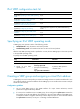
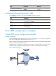
Multiple VRRP groups configuration example
To implement load sharing between the VRRP groups, you must manually configure the default gateway
10 .1.1.111 f o r s o m e h o s t s a n d 10 .1.1.112 for the other on the subnet 10.1.1.0/24.
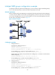
Network requirements
Router A and Router B form two VRRP groups to implement load sharing and mutual backup. VRRP group
1 uses the virtual IP address 10.1.1.111/24 to provide gateway service for some hosts on the subnet
10.1.1.0/24, and VRRP group 2 uses the virtual IP address 10.1.1.112/24 to provide gateway service for
the other hosts on the subnet, as shown in Figure 15.
Figure 15 Network diagram
Configuration procedure
1. Configure Router A:
# Specify an IP address for Router A.
<RouterA> system-view
[RouterA] interface gigabitethernet 2/0/1
[RouterA-GigabitEthernet2/0/1] ip address 10.1.1.1 255.255.255.0
# Create VRRP group 1 and set its virtual IP address to 10.1.1.111.
[RouterA-GigabitEthernet2/0/1] vrrp vrid 1 virtual-ip 10.1.1.111
# Assign Router A a higher priority than Router B in VRRP group 1, so Router A can become the
master in the group.
[RouterA-GigabitEthernet2/0/1] vrrp vrid 1 priority 110
# Create VRRP group 2, and set its virtual IP address to 10.1.1.112.
[RouterA-GigabitEthernet2/0/1] vrrp vrid 2 virtual-ip 10.1.1.112
2. Configure Router B:
# Specify an IP address for Router B.
<RouterB> system-view
[RouterB] interface gigabitethernet 2/0/1
[RouterB-GigabitEthernet2/0/1] ip address 10.1.1.2 255.255.255.0
# Create VRRP group 1, and set its virtual IP address to 10.1.1.111.