
R0106-HP MSR Router Series High Availability Configuration Guide(V7)

44
IPv6 VRRP configuration examples
Single VRRP group configuration example
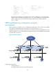
Network requirements
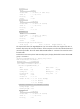
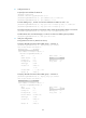
Router A and Router B form a VRRP group, and use the virtual IP addresses 1::10/64 and FE80::10 to
provide gateway service for the subnet where Host A resides, as shown in Figure 17.
Host A lear
ns 1::10/64 as its default gateway from RA messages sent by the routers.
Router A operates as the master to forward packets from Host A to Host B. When Router A fails, Router
B takes over to forward packets for Host A.
Figure 17 Network diagram
Configuration procedure
1. Configure Router A:
# Specify an IPv6 address for Router A.
<RouterA> system-view
[RouterA] interface gigabitethernet 2/0/1
[RouterA-GigabitEthernet2/0/1] ipv6 address fe80::1 link-local
[RouterA-GigabitEthernet2/0/1] ipv6 address 1::1 64
# Create VRRP group 1, and set its virtual IPv6 addresses to FE80::10 and 1::10.
[RouterA-GigabitEthernet2/0/1] vrrp ipv6 vrid 1 virtual-ip fe80::10 link-local
[RouterA-GigabitEthernet2/0/1] vrrp ipv6 vrid 1 virtual-ip 1::10
# Assign Router A a higher priority than Router B in VRRP group 1, so Router A can become the
master.
[RouterA-GigabitEthernet2/0/1] vrrp ipv6 vrid 1 priority 110
# Configure Router A to operate in preemptive mode, so it can become the master whenever it
operates correctly, and set the preemption delay to 5 seconds to avoid frequent status switchover.
[RouterA-GigabitEthernet2/0/1] vrrp ipv6 vrid 1 preempt-mode delay 5
# Enable Router A to send RA messages, so Host A can learn the default gateway address.
[RouterA-GigabitEthernet2/0/1] undo ipv6 nd ra halt