
R0106-HP MSR Router Series High Availability Configuration Guide(V7)

47
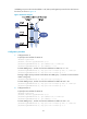
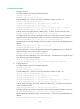
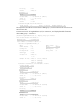
and VRRP group 2 uses the virtual IP address 1::20/64 to provide gateway service for the other hosts on
the subnet, as shown in Figure 18.
Figure 18 Network diagram
Configuration procedure
1. Configure Router A:
# Specify an IPv6 address for Router A.
<RouterA> system-view
[RouterA] interface gigabitethernet 2/0/1
[RouterA-GigabitEthernet2/0/1] ipv6 address fe80::1 link-local
[RouterA-GigabitEthernet2/0/1] ipv6 address 1::1 64
# Create VRRP group 1, and set its virtual IPv6 addresses to FE80::10 to 1::10.
[RouterA-GigabitEthernet2/0/1] vrrp ipv6 vrid 1 virtual-ip fe80::10 link-local
[RouterA-GigabitEthernet2/0/1] vrrp ipv6 vrid 1 virtual-ip 1::10
# Assign a higher priority to Router A than Router B in VRRP group 1, so Router A can become the
master in the group.
[RouterA-GigabitEthernet2/0/1] vrrp ipv6 vrid 1 priority 110
# Create VRRP group 2, and set its virtual IPv6 addresses to FE80::20 and 1::20.
[RouterA-GigabitEthernet2/0/1] vrrp ipv6 vrid 2 virtual-ip fe80::20 link-local
[RouterA-GigabitEthernet2/0/1] vrrp ipv6 vrid 2 virtual-ip 1::20
2. Configure Router B:
# Specify an IPv6 address for Router B.
<RouterB> system-view
[RouterB] interface gigabitethernet 2/0/1
[RouterB-GigabitEthernet2/0/1] ipv6 address fe80::2 link-local
[RouterB-GigabitEthernet2/0/1] ipv6 address 1::2 64
# Create VRRP group 1, and set its virtual IPv6 addresses to FE80::10 and 1::10.
[RouterB-GigabitEthernet2/0/1] vrrp ipv6 vrid 1 virtual-ip fe80::10 link-local
[RouterB-GigabitEthernet2/0/1] vrrp ipv6 vrid 1 virtual-ip 1::10