
R0106-HP MSR Router Series High Availability Configuration Guide(V7)

78
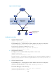
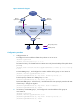
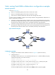
Figure 22 Network diagram
Configuration procedure
1. Configure VRRP on Router A:
<RouterA> system-view
[RouterA] interface gigabitethernet 2/0/1
# Create VRRP group 1, and configure the virtual IP address 192.168.0.10 for the group.
[RouterA-GigabitEthernet2/0/1] vrrp vrid 1 virtual-ip 192.168.0.10
# Set the priority of Router A in VRRP group 1 to 110.
[RouterA-GigabitEthernet2/0/1] vrrp vrid 1 priority 110
[RouterA-GigabitEthernet2/0/1] return
2. Configure BFD on Router B:
# Configure the source address of BFD echo packets as 10.10.10.10.
<RouterB> system-view
[RouterB] bfd echo-source-ip 10.10.10.10
# Create track entry 1, and associate it with the BFD session to verify the reachability of Router A.
[RouterB] track 1 bfd echo interface gigabitethernet 2/0/1 remote ip 192.168.0.101
local ip 192.168.0.102
3. Configure VRRP on Router B:
# Create VRRP group 1, and configure the virtual IP address 192.168.0.10 for the group.
[RouterB] interface gigabitethernet 2/0/1
[RouterB-GigabitEthernet2/0/1] vrrp vrid 1 virtual-ip 192.168.0.10
# Associate VRRP group 1 with track entry 1.
[RouterB-GigabitEthernet2/0/1] vrrp vrid 1 track 1 switchover
[RouterB-GigabitEthernet2/0/1] return
Internet
Virtual router
Virtual IP address:
192.168.0.10
GE2/0/1
192.168.0.101/24
GE2/0/1
192.168.0.102/24
Router A
Master
Router B
Backup
L2 switch
VRRP packets
BFD probe packets