
R0106-HP MSR Router Series Interface Command Reference(V7)

48
clock { dceclk1 | dceclk2 | dceclk3 }
undo clock
Default
The DTE-side clock is dteclk1 and the DCE-side clock is dceclk1.
Views
Synchronous serial interface view
Predefined user roles
network-admin
Parameters
dteclk1: Sets the interface clock selection mode to DTE clock option 1.
dteclk2: Sets the interface clock selection mode to DTE clock option 2.
dteclk3: Sets the interface clock selection mode to DTE clock option 3.
dteclk4: Sets the interface clock selection mode to DTE clock option 4.
dteclk5: Sets the interface clock selection mode to DTE clock option 5.
dteclkauto: Sets the interface clock selection mode to DTE auto-negotiation.
dceclk1: Sets the interface clock selection mode to DCE clock option 1.
dceclk2: Sets the interface clock selection mode to DCE clock option 2.
dceclk3: Sets the interface clock selection mode to DCE clock option 3.
Usage guidelines
In DTE mode, the synchronous serial interface supports the clock { dteclk1 | dteclk2 | dteclk3 | dteclk4
| dteclk5 | dteclkauto } command.
In DCE mode, the synchronous serial interface supports the clock { dceclk1 | dceclk2 | dceclk3 }
command.
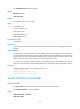
A synchronous serial interface can operate as a DCE or DTE.
• As a DCE, the interface provides the DCEclk clock for the DTE.
• As a DTE, the interface accepts the clock provided by the DCE. Because transmitting and receiving
clocks of synchronization devices are independent, the receiving clock of a DTE device can be
either the transmitting or receiving clock of the DCE device. The transmitting clock of a DTE device
can be either the transmitting or receiving clock of the DCE device. Therefore, five clock options are
available for a DTE device.
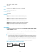
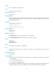
In Figure 1, "TxC
lk" represents transmitting clock, and "RxClk" represents receiving clock.
Figure 1 Selecting a clock for a synchronous serial interface