HP MSR Router Series Interface Configuration Guide(V7) Part number: 5998-5674 Software version: CMW710-R0106 Document version: 6PW100-20140607
Legal and notice information © Copyright 2014 Hewlett-Packard Development Company, L.P. No part of this documentation may be reproduced or transmitted in any form or by any means without prior written consent of Hewlett-Packard Development Company, L.P. The information contained herein is subject to change without notice.
Contents Bulk configuring interfaces ·········································································································································· 1 Configuration restrictions and guidelines ······················································································································· 1 Configuration procedure ··················································································································································
Configuring an E1-F interface in framed mode·································································································· 27 Configuring an E1-F interface in unframed mode ····························································································· 27 Configuring other E1-F interface parameters ····································································································· 28 Displaying and maintaining E1-F interfaces ······························
Configuring ATM interfaces ······································································································································ 55 Overview········································································································································································· 55 ATM and DSL ·························································································································································
Bulk configuring interfaces You can enter interface range view to bulk configure multiple interfaces with the same feature instead of configuring them one by one. For example, you can execute the shutdown command in interface range view to shut down a range of interfaces. Configuration restrictions and guidelines When you bulk configure interfaces in interface range view, follow these restrictions and guidelines: • In interface range view, only the commands supported by the first interface are available.
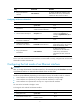
Step Command Remarks 3. (Optional.) Display commands available for the first interface in the interface range. Enter a question mark (?) at the interface range prompt. N/A 4. Use available commands to configure the interfaces. Available commands vary by interface. N/A 5. (Optional.) Verify the configuration. display this N/A Displaying and maintaining bulk interface configuration Execute the display command in any view.
Configuring Ethernet interfaces In this chapter,"MSR2000" refers to MSR2003. "MSR3000" collectively refers to MSR3012, MSR3024, MSR3044, MSR3064. "MSR4000" collectively refers to MSR4060 and MSR4080. Your device supports the following types of Ethernet interfaces: • Layer 2 Ethernet interfaces—Physical Ethernet interfaces operating at the data link layer (Layer 2) to switch packets. • Layer 3 Ethernet interfaces—Physical Ethernet interfaces operating at the network layer (Layer 3) to route packets.
Changing the active port of a combo interface Step Command Remarks 1. Enter system view. system-view N/A 2. Enter Ethernet interface view. interface interface-type interface-number N/A 3. Activate the copper combo port or fiber combo port. combo enable { copper | fiber } By default, the copper combo port is active.
Step Command Remarks 8. Bring up the Ethernet interface. undo shutdown By default, the Ethernet interface on the MSR 3600 routers are up. The Ethernet interface on other routers are down. Configuring an Ethernet subinterface Step Command Remarks 1. Enter system view. system-view N/A 2. Create an Ethernet subinterface. interface interface-type interface-number.subnumber N/A 3. Set the interface description. description text The default setting is interface-name Interface.
Step Command 3. Change the link mode of the Ethernet interface. Remarks By default, the following interfaces operate as Layer 2 Ethernet interfaces: port link-mode { bridge | route } Ethernet interfaces on a SIC-4FSW, SIC-4GSW, DSIC-9FSW, HMIM-8GSW, or HMIM-24GSW interface card. Configuring jumbo frame support An Ethernet interface might receive some frames larger than the standard Ethernet frame size (called "jumbo frames") during high-throughput data exchanges, such as file transfers.
After a flapping interface is dampened, it does not report its state changes to the CPU. For state change events, the interface only generates SNMP notifications and log messages. Parameters • Penalty—The interface has a initiate penalty of 0. When the interface flaps, it is assigned a penalty of 1000 for each down even, and does not increase for up events. • Ceiling—The penalty stops increasing after it reaches the ceiling.
Configuration procedure To configure dampening on an Ethernet interface: Step Command Remarks 1. Enter system view. system-view N/A 2. Enter Ethernet interface view. interface interface-type interface-number N/A 3. Enable dampening on the interface. dampening [ half-life reuse suppress max-suppress-time ] By default, interface dampening is disabled on Ethernet interfaces.
suspends sending packets to the peer. When congestion occurs, the interface cannot send flow control frames to the peer. To handle unidirectional traffic congestion on a link, configure the flow-control receive enable command at one end and the flow-control command at the other end. To enable both ends of a link to handle traffic congestion, configure the flow-control command at both ends. To enable generic flow control on an Ethernet interface: Step Command Remarks 1. Enter system view.
Configuration procedure To set storm suppression thresholds on one or multiple Ethernet interfaces: Step Command Remarks 1. Enter system view. system-view N/A 2. Enter Ethernet interface or subinterface view. interface interface-type { interface-number | interface-number.subnumber } N/A 3. Enable broadcast suppression and set the broadcast suppression threshold. broadcast-suppression { ratio | pps max-pps } By default, broadcast traffic is allowed to pass through an interface. 4.
Step Command Remarks 2. Enter Ethernet interface view. interface interface-type interface-number N/A 3. Set the MDIX mode of the Ethernet interface. mdix-mode { automdix | mdi | mdix } By default, a copper Ethernet interface operates in auto mode to negotiate pin roles with its peer. Configuring a Layer 3 Ethernet interface or subinterface Setting the MTU for an Ethernet interface or subinterface The value of maximum transmission unit (MTU) affects the fragmentation and reassembly of IP packets.
Displaying and maintaining an Ethernet interface or subinterface Execute display commands in any view and reset commands in user view. Task Command Display interface traffic statistics. display counters { inbound | outbound } interface [ interface-type [ interface-number | interface-number.subnumber ] ] Display traffic rate statistics of interfaces in up state over the last sampling interval. display counters rate { inbound | outbound } interface [ interface-type [ interface-number | interface-number.
Configuring WAN interfaces This chapter describes how to configure interfaces for connecting to WAN networks, including ATM and ISDN. Available WAN interfaces include the asynchronous serial interface, synchronous serial interface, ATM interface, ISDN BRI interface, and CE1/PRI interface. For more information about ATM interfaces, see "Configuring ATM interfaces.
Configuring an asynchronous serial interface This section only describes the interface properties configuration. Depending on the network requirements, you might also need to configure PPP, DDR, IP address, firewall, and interface backup. To configure an asynchronous serial interface: Step Command Remarks 1. Enter system view. system-view N/A 2. Enter asynchronous serial interface view. 3. (Optional.) Set the interface description.
Configuring a synchronous serial interface This section only describes the interface properties configuration. Depending on the network requirements, you might also need to configure the data link layer protocol, DDR, IP address, firewall, and interface backup. To configure a synchronous serial interface: Step Command Remarks 1. Enter system view. system-view N/A 2. Enter synchronous serial interface view.
Step Command Remarks 16. Configure the polling interval. timer-hold seconds The default is 10 seconds. 17. Set the line idle-code. idle-code { 7e | ff } The default is 0x7E. 18. (Optional.) Enable RTS signal reverse. reverse-rts By default, RTS signal reverse is disabled. 19. (Optional.) Set the intended bandwidth for the synchronous serial interface. bandwidth bandwidth-value By default, the expected bandwidth (in kbps) is the interface baud rate divided by 1000. 20. (Optional.
Configuration procedure The AM interface supports all commands available on the asynchronous interface and the modem, except for the modem auto-answer and baudrate commands. For more information about modem configuration, see Layer 2—WAN Configuration Guide. In addition, to set the baud rate for an AM interface, you must use the speed command in user line view. For more information, see Fundamentals Configuration Guide. This section only describes the interface properties configuration.
Step Command Remarks 13. Bring up the AM interface. undo shutdown By default, an AM interface is up. Displaying and maintaining AM interfaces Execute the display command in any view and the reset command in user view. Task Command Display AM interface information. display interface [ analogmodem [ interface-number ] ] [ brief [ description | down ] ] Clear statistics for AM interfaces.
Figure 2 Referential ISDN user-network interface configuration Configuration prerequisites Before you configure an ISDN BRI interface, verify the following items: • Interface type (ISDN BRI U or ISDN BRI S/T) provided by your telecom service provider—You must identify this information before you purchase a router. You must perform this task because the UNI implementation of a service provider might deviate from ITU-T I.411. • Availability of digital service—The router requires digital transmission.
Step Command Remarks 7. Set the intended bandwidth for the BRI interface. bandwidth bandwidth-value By default, the expected bandwidth (in kbps) is the interface baud rate divided by 1000. 8. (Optional.) Restore the default settings for the BRI interface. default N/A 9. (Optional.) Bring up the BRI interface. undo shutdown By default, a BRI interface is up. 10. (Optional.) Activate the BRI interface. By default, a BRI interface is not activated.
Configuring a CE1/PRI interface in E1 mode Step Command Remarks 1. Enter system view. system-view N/A 2. Enter CE1/PRI interface view. controller e1 number N/A 3. Configure the interface to operate in E1 mode. using e1 By default, a CE1/PRI interface operates in CE1/PRI mode. 4. (Optional.) Configure the interface to perform alarm indication signal (AIS) test. detect-ais 5. (Optional.) Set other interface parameters. See "Configuring other CE1/PRI interface parameters." Optional.
• Data link protocols, such as PPP and HDLC. • IP addressing. • Interface backup settings if the interface is used as a primary or backup interface. • NAT and packet filtering if a firewall is to be set up. Configuring a CE1/PRI interface in PRI mode Step Command Remarks 1. Enter system view. system-view N/A 2. Enter CE1/PRI interface view. controller e1 number N/A 3. Configure the interface to operate in CE1/PRI mode. using ce1 The default operating mode is CE1/PRI mode.
Step Command Remarks 6. Set the cable type. cable { long | short } The default cable setting is long mode. 7. Set the clock mode. clock { master | slave } The default clock mode is slave, which is line clock. 8. Enable automatic clock mode change. clock-change auto By default, automatic clock mode change is disabled. 9. Set the line idle code type. Idle-code { 7e | ff } The default is 0x7E. By default: 10. Set the type and the number of interframe filling tags.
• When it is operating as a PRI interface, you can choose a group of timeslots (except for timeslot 24) as the B channel. Timeslot 24 is the D channel for signaling transmission. You can bundle the B channel and the D channel to form a PRI set. For the PRI set, an ISDN PRI interface is created automatically. Configuring a CT1/PRI interface in CT1 mode Step Command Remarks 1. Enter system view. system-view N/A 2. Enter CT1/PRI interface view.
For the PRI set, the system automatically creates a serial interface numbered serial number:23. This interface has the same logical features as an ISDN PRI interface and supports the following configurations: • DDR. • PPP and PPP authentication. • IP addressing. • Interface backup settings if the interface is used as a primary or backup interface. • Firewall. Configuring other CT1/PRI interface parameters Step Command Remarks 1. Enter system view. system-view N/A 2.
Step Command Remarks 15. Restore the default settings for the CT1/PRI interface. default N/A 16. (Optional.) Bring up the CT1/PRI interface. undo shutdown By default, a CT1/PRI interface is up. 17. Enter the view of the synchronous serial interface created on the CT1/PRI interface. 18. Set the CRC mode. interface serial interface-number:set-number or N/A interface serial interface-number:23 crc { 16 | 32 | none } By default, 16-bit CRC is adopted.
Configuring an E1-F interface E1-F interfaces, which are fractional E1 interfaces, are simplified CE1/PRI interfaces. They are a cost-effective alternative to CE1/PRI interfaces where E1 access does not require multiple channel sets or ISDN PRI. An E1-F interface has these features: • In framed mode, an E1-F interface can bind timeslots into only one channel set. In contrast, a CE1/PRI interface can group and bundle timeslots randomly into multiple channel sets.
Step Command Remarks 5. (Optional.) Set other interface parameters. See "Configuring other E1-F interface parameters." N/A Configuring other E1-F interface parameters Step Command Remarks 1. Enter system view. system-view N/A 2. Enter E1-F interface view. interface serial serial-number N/A 3. Configure the interface description. description text By default, the description of an interface is interface-name Interface. 4. Set the line code format.
Task Command Display information about E1-F interfaces. display fe1 [ serial interface-number ] Display the status of an E1-F interface. display interface serial interface-number Clear statistics for E1-F interfaces. reset counters interface [ serial [ interface-number ] ] Configuring a T1-F interface T1-F interfaces, fractional T1 interfaces, are simplified CT1/PRI interfaces.
Step Command Remarks 8. Set the clock mode. ft1 clock { master | slave } The default is slave, which is line clock. 9. Set the framing format. ft1 frame-format { esf | sf } The default is esf. 10. (Optional.) Enable RAI detection on the interface. ft1 alarm-detect rai 11. Set the type of line idle code. ft1 idle-code { 7e | ff } By default, RAI detection is enabled on the interface. This command is applicable when the framing format is ESF. The default is 0x7E. By default: 12.
Step Command Remarks 22. (Optional.) Restore the default settings for the T1-F interface. default N/A 23. Bring up the T1-F interface. undo shutdown By default, a T1-F interface is up. Starting a BERT test on a T1-F interface BERT operates as follows: 1. The local end sends out a pattern, which is looped over on the line and sent back to the local end. 2. The local end checks the received pattern for the bit error rate to help determine the line condition.
framing signal transmission and does not support bundling. All other timeslots can be randomly bundled into n × 64 kbps channels, where n is the number of bundled timeslots. A CE3 interface can be channelized into E1 lines in framed mode or unframed mode. { { • When an E1 line is operating in unframed (E1) mode, the system automatically creates a 2048-kbps synchronous serial interface numbered serial number/line-number:0 for it.
Step Command Remarks 14. Set the CRC mode. crc { 16 | 32 | none } By default, 16-bit CRC is adopted. Configuring a CE3 interface in CE3 mode When you change the interface state during the configuration, make sure you understand the following information: • Shutting down or bringing up a CE3 interface also shuts down or brings up all its lines and serial interfaces, including: { E1 lines demultiplexed from the CE3 interface. { Serial interfaces created for unframed E1 lines.
Step Command Remarks • For the CE3 interface: clock { master | slave } 7. (Optional.) Set the clock mode. • For an E1 line: The default mode for both the CE3 interface and E1 line is slave, which is line clock. national-bit { 0 | 1 } The default is 1. e1 line-number set clock { master | slave } 8. (Optional.) Set the national bit. • For the CE3 interface: 9. (Optional.) Enable loopback. loopback { local | payload | remote } • For an E1 line: By default, loopback is disabled.
• In T3 mode, a CT3 interface is a synchronous serial interface with 44.736 Mbps of data bandwidth. No timeslots are divided. • In CT3 mode, a CT3 interface can be demultiplexed into 28 channels of T1 signals. Each T1 line can be divided into 24 timeslots numbered 1 through 24. Each line on a T1 interface can operate at either 64 kbps or 56 kbps. The following are schemes available for creating different rates of T1 lines on a CT3 interface in CT3 mode, as follows: • M × 1.
Step Command 12. (Optional.) Configure FEAC channel signal detection/sending on the CT3 interface. • feac detect • feac generate loopback { ds3-line | ds3-payload } • feac generate { ds3-los | ds3-ais | ds3-oof | ds3-idle | ds3-eqptfail } Remarks By default, FEAC channel signal detection is enabled, but no FEAC signals are sent. 13. (Optional.) Configure MDL message detection/sending on the CT3 interface.
Step Command Remarks 1. Enter system view. system-view N/A 2. Enter CT3 interface view. controller t3 interface-number N/A 3. Configure the interface to operate in CT3 mode. using ct3 The default operating mode is CT3 mode. • Method 1: Set the operating mode to unframed (T1) mode: t1 line-number unframed • Method 2: 4. Set the operating mode of a T1 line on the CT3 interface to unframed mode or framed mode.
Step Command Remarks • On the CT3 interface: 12. (Optional.) Start a BERT test. bert pattern { 2^7 | 2^11 | 2^15 | qrss } time number [ unframed ] • On a T1 line: By default, BERT test is disabled. t1 line-number bert pattern { 2^11 | 2^15 | 2^20 | 2^23 | qrss } time number [ unframed ] 13. (Optional.) Configure FEAC channel signal detection/sending on the CT3 interface.
• Network layer protocols, such as IP. Displaying and maintaining CT3 interfaces Execute display commands in any view and reset commands in user view. Task Command Display CT3 interface information. display controller t3 [ interface-number ] Display the configuration and state of a serial interface formed on a CT3 interface. display interface serial interface-number Display the state of a T1 line. t1 line-number show Clear statistics for CT3 interfaces.
Configuring POS interfaces This chapter describes how to configure physical parameters for POS interfaces, including standard POS interfaces and POS channel interfaces. Before you configure the link and network layer parameters on a POS interface, you must perform the tasks in this chapter to configure its physical parameters. Overview Packet over SONET/SDH (POS) is a technology widely used on WAN and MAN. It supports data packets such as IP packets.
Step Command Remarks 3. Configure the interface description. description text By default, the description of a POS interface is interface name Interface, for example, Pos2/2/0 Interface. 4. Set the keepalive interval. timer-hold seconds The default setting is 10 seconds. 5. Set the clock mode. clock { master | slave } The default setting is slave. 6. Set the CRC length. crc { 16 | 32 } The default setting is 32 bits. 7. Set the loopback mode.
Configuring a POS channel interface POS channel interfaces are created through channelization of a high-speed CPOS interface. They work in the same way as POS interfaces. For more information about creating POS channel interfaces, see "Configuring CPOS interfaces." To configure a POS channel interface: Step Command Remarks 1. Enter system view. system-view N/A 2. Enter POS channel interface view. interface pos interface-number N/A 3. Configure the interface description.
Task Command Clear statistics for POS interfaces. reset counters interface [ pos interface-number ] POS interface configuration example Network requirements As shown in Figure 3, POS interfaces on Router A and Router B are connected through a pair of single-mode optical fibers for data transmission. Figure 3 Network diagram Configuration procedure 1. Configure POS 2/2/0 on Router A: # Assign an IP address to the interface.
Verifying the configuration # Verify the POS interface settings, for example, on Router A. display interface pos # Verify that Router A and Router B can ping each other at the POS interfaces. (Details not shown.) Troubleshooting POS interfaces Symptom 1 The physical state of the POS interface is down. Solution To resolve the problem: • Verify that the POS interface is connected correctly to the remote port.
• If the problem persists, contact HP Support.
Configuring CPOS interfaces Overview The low-speed tributary signals multiplexed to form an SDH signal are called channels. The channelized POS (CPOS) interface makes full use of SDH to provide the following benefits: • Provides precise bandwidth division. • Reduces the number of low-speed physical interfaces on devices. • Enhances aggregation capacity. • Improves the access capacity of leased lines. The device supports the CPOS interfaces in Table 1.
Higher-order path overhead monitors paths at the VC-4/VC-3 level. Similar to the J0 byte, the higher-order VC-N path trace byte J1 is included in the higher-order path overhead to repeatedly send the higher-order path access point identifier. The receiving end of the path uses this identifier to make sure it is in continuous connection with the specified sender. The sender and the receiver must use the same J1 byte.
CPOS interface configuration task list Task at a glance Configure a CPOS E1 interface: • (Required.) Configuring the operating mode of an interface card • (Required.) Configuring basic functions of a CPOS interface • (Required.) Configuring an E1 channel Configure a CPOS T1 interface: • (Required.) Configuring the operating mode of an interface card • (Required.) Configuring basic functions of a CPOS interface • (Required.
Step Command Remarks By default: 8. Configure the SOH and higher-order path overhead bytes. flag { c2 path-number c2-value | s1 s1-value | s1s0 path-number s1s0-value } flag { j0 | j1 path-number } { sdh | sonet } flag-value • c2 is 0x02. • s1 is 0x0f. • s1s0 is 0x00 for SONET and 0x02 for SDH. • j0 is 0x01 for SONET and a 16-byte empty character string for SDH. • j1 is a 64-byte empty character string for SONET and a 16-byte empty character string for SDH. 9.
Step Command Remarks • Specify the unframed mode: e1 e1-number unframed • Specify the framed mode and 7. Configure the E1 operating mode. bundle timeslots: a. (Optional.) undo e1-number unframed e1 b. e1 e1-number channel-set set-number timeslot-list range 8. (Optional.) Shut down the specified E1 channel. e1 e1-number shutdown By default, an E1 channel operates in framed mode and is not channelized. When you place an E1 channel in unframed mode, the system automatically creates a 2.
Step Command Remarks • Specify the unframed mode: By default, a T1 channel operates in framed mode and is not channelized. t1 t1-number unframed • Specify the framed mode and bundle timeslots: 7. Configure the T1 operating mode. a. (Optional.) undo t1-number unframed t1 b. t1 t1-number channel-set set-number timeslot-list range [ speed { 56k | 64k } ] 8. (Optional.) Shut down specified T1 channel.
Figure 5 Network diagram Router H E1 Router A SDH CPOS2/4/0 E1 Router B Configuration procedure IMPORTANT: For correct network synchronization, make sure the master clock mode is configured on the SONET/SDH devices connected to the routers. 1. Configure Router A: # Configure E1 channels 1 and 2 of CPOS 2/4/0 to operate in unframed mode.
# Create MP-group 1 and assign an IP address to it. [RouterB] interface mp-group 1 [RouterB-Mp-group1] ip address 10.1.1.2 24 [RouterB-Mp-group1] quit # Assign Serial 2/4/1:0 to MP-group 1. [RouterB] interface serial2/4/1:0 [RouterB-Serial2/4/1:0] ppp mp mp-group 1 [RouterB-Serial2/4/1:0] quit # Assign Serial 2/4/2:0 to MP-group 1.
2. Verify that the router and its directly connected SDH device have the same multiplex path for E1 channels. (Details not shown.) 3. Debug the loop condition. debugging ppp lcp error 4. If the problem persists, contact HP Support.
Configuring ATM interfaces ATM interface features are applicable to routers installed with ATM-OC3, ADSL2+, G.shdsl, or G.shdsl.Bis interface cards. Overview ATM and DSL Asynchronous Transfer Mode (ATM) is a technology based on packet transmission mode and incorporates the high-speed of circuit transmission mode. It is a backbone network technology for transmission of audio, video, and data.
• Variable Bit Rate-Real Time (VBR-RT). • Variable Bit Rate-Non Real Time (VBR-NRT). • Permanent Virtual Circuit (PVC). • Traffic Shaping based on Virtual Circuit (VC). • User-to-Network Interface (UNI). • RFC1483, Multiprotocol Encapsulation over ATM Adaptation Layer 5. • RFC 2225, Classical IP and ARP over ATM. • RFC 2390, Inverse Address Resolution Protocol. • F5 End to End Loopback OAM. • ATM Adaptation Layer 5 (AAL5).
Step Command Remarks 10. Configure an MTU value for the interface. mtu size By default, the MTU value for the interface is 1500 bytes. 11. (Optional.) Restore the default of the interface. default N/A 12. Bring up the interface. undo shutdown By default, the interface is up. Configuring an ADSL interface Overview ADSL is an asymmetric transmission technology that implements high-speed data transmission over twisted-pair copper wire.
Figure 6 Network diagram IMPORTANT: When you connect ADSL interfaces, use standard twisted pairs and correctly connect the cables. This section covers only the physical configurations of ADSL interfaces (including ATM ADSL and ATM ADSL 2+ interfaces). For information about configuring ATM services, see Layer 2—WAN Configuration Guide. Configuration procedure To configure an ADSL interface: Step Command Remarks 1. Enter system view. system-view N/A 2. Enter view.
Step Command Remarks 9. (Optional.) Restore the default of the interface. default N/A 10. Bring up the interface. undo shutdown By default, the interface is up. Configuring a G.SHDSL interface Overview G.SHDSL is a symmetric transmission technology that implements high-speed data transmission over the twisted-pair copper wire by using unused high frequency ranges with a different modulation method. Based on the maximum wire pairs supported on an interface, the G.
Step Command Remarks • Configure the connection 6. Configure the connection mode for the interface. mode for four-wire G.SHDSL.BIS interfaces: shdsl wire { 2 | 4-auto-enhanced | 4-enhanced | 4-standard } • Configure the connection mode for eight-wire G.SHDSL.BIS interface: shdsl wire { 2 | 4-enhanced | 4-standard | 6 | 8 | auto } 7. Configure operating mode for the interface. shdsl mode { co | cpe } Use either method. By default: • A four-wire G.SHDSL.
Step Command Remarks 17. (Optional.) Restore the default of the interface. default N/A By default, the interface is up. 18. Bring up the interface. undo shutdown HP recommends that you shut down the unused G.SHDSL interfaces to save system resources. Configuring an ATM subinterface An ATM subinterface supports the same network layer functions as an ATM interface. The network layers of different ATM subinterfaces are independent of each other.
No dedicated but multi-purpose EFM cards are available. Switch the operating mode of an interface card as needed. For more information about the operating modes of an interface card, see Fundamentals Configuration Guide. This section covers only the physical configurations of the EFM interface. You can also configure ARP, DHCP, IP address, and firewall on an EFM interface. To configure an EFM interface: Step Command Remarks 1. Enter system view. system-view N/A 2. Enter EFM interface view.
Step Command Remarks 13. (Optional.) Enable SHDSL line probing. shdsl line-probing enable By default, SHDSL line probing is enabled. 14. Configure the expected bandwidth for the interface. bandwidth bandwidth-value By default, the expected bandwidth (in kbps) is calculated with the following formula: Interface baud rate/1000. 15. Configure an MTU value for the interface. mtu size By default, the MTU value for the interface is 1500 bytes. 16. (Optional.) Restore the default of the interface.
Task Command Display DSL version information and available capabilities. display dsl version interface atm interface-number Clear the statistics for an interface. reset counters interface [ atm [ interface-number ] ] Troubleshooting ATM interfaces Interface state error Symptom The ATM interface state is down. Solution Verify that the Rx and Tx ends of the optical fiber are correctly connected.
3. Use the debugging physical command to view details about activation, such as issuing of the activate command, activation timeout, training process, and activation success. 4. If line activation attempts always fail, verify that the line is securely connected and functioning correctly. 5. If bit error rate is high or interference occurs too often, shut down and then bring up the interface by using the shutdown and undo shutdown commands. You can also reboot the device and reconnect the line.
Configuring loopback, null, and inloopback interfaces This chapter describes how to configure a loopback interface, a null interface, and an inloopback interface. Configuring a loopback interface A loopback interface is a virtual interface. The physical layer state of a loopback interface is always up unless the loopback interface is manually shut down.
Configuring a null interface A null interface is a virtual interface and is always up, but you cannot use it to forward data packets or configure it with an IP address or link layer protocol. The null interface provides a simpler way to filter packets than ACL. You can filter undesired traffic by transmitting it to a null interface instead of applying an ACL.
Support and other resources Contacting HP For worldwide technical support information, see the HP support website: http://www.hp.
Conventions This section describes the conventions used in this documentation set. Command conventions Convention Description Boldface Bold text represents commands and keywords that you enter literally as shown. Italic Italic text represents arguments that you replace with actual values. [] Square brackets enclose syntax choices (keywords or arguments) that are optional. { x | y | ... } Braces enclose a set of required syntax choices separated by vertical bars, from which you select one.
Network topology icons Represents a generic network device, such as a router, switch, or firewall. Represents a routing-capable device, such as a router or Layer 3 switch. Represents a generic switch, such as a Layer 2 or Layer 3 switch, or a router that supports Layer 2 forwarding and other Layer 2 features. Represents an access controller, a unified wired-WLAN module, or the switching engine on a unified wired-WLAN switch. Represents an access point. Represents a mesh access point.
Index CDFOPRT Contacting HP,68 C Conventions,69 Configuration procedure,1 CPOS interface configuration task list,48 Configuration restrictions and guidelines,1 CPOS-E1 interface configuration example,51 Configuring a CE1/PRI interface,20 Configuring a CE3 interface,31 D Configuring a CT1/PRI interface,23 Displaying and maintaining an Ethernet interface or subinterface,12 Configuring a CT3 interface,34 Displaying and maintaining ATM interfaces,63 Configuring a G.