
R0106-HP MSR Router Series Interface Configuration Guide(V7)

23
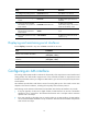
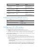
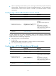
Step Command Remarks
6. Set the cable type.
cable { long | short }
The default cable setting is long
mode.
7. Set the clock mode.
clock { master | slave }
The default clock mode is slave,
which is line clock.
8. Enable automatic clock mode
change.
clock-change auto
By default, automatic clock mode
change is disabled.
9. Set the line idle code type.
Idle-code { 7e | ff } The default is 0x7E.
10. Set the type and the number of
interframe filling tags.
itf { number number | type { 7e |
ff } }
By default:
• The type of the interframe filling
tag is 0x7E.
• The number of interframe filling
tags is four.
11. Set the loopback mode.
loopback { local | payload |
remote }
By default, loopback is disabled.
12. Restore the default settings for
the CE1/PRI interface.
default Optional.
13. Bring up the CE1/PRI
interface.
undo shutdown
By default, a CE1/PRI interface is
up.
14. Return to system view.
quit N/A
15. Enter the view of the
synchronous serial interface
created on the CE1/PRI
interface.
interface serial
interface-number:set-number
or
interface serial
interface-number:15
N/A
16. Set the CRC mode
crc { 16 | 32 | none } By default, 16-bit CRC is adopted.
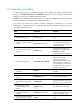
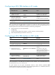
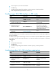
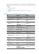
Displaying and maintaining CE1/PRI interfaces
Execute display commands in any view and the reset command in user view.
Task Command
Display information about CE1/PRI interfaces.
display controller e1 [interface-number ]
Display information about a channel set or PRI set.
display interface serial interface-number:set-number
Clear statistics for CE1/PRI interfaces. reset counters controller e1 [ interface-number ]
Configuring a CT1/PRI interface
A CT1/PRI interface can operate only in channelized mode. You can use the interface in the following
ways:
• When it is operating as a CT1 interface, you can divide all the timeslots (numbered 1 to 24)
randomly into groups. Each of these groups can form one channel set. For each channel set, the
system automatically creates a synchronous serial interface.