
R0106-HP MSR Router Series Interface Configuration Guide(V7)


43
Task Command
Clear statistics for POS interfaces. reset counters interface [ pos interface-number ]
POS interface configuration example
Network requirements
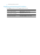
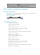
As shown in Figure 3, POS interfaces on Router A and Router B are connected through a pair of
single-mode optical fibers for data transmission.
Figure 3 Network diagram
Configuration procedure
1. Configure POS 2/2/0 on Router A:
# Assign an IP address to the interface.
<RouterA> system-view
[RouterA] interface pos 2/2/0
[RouterA-Pos2/2/0] ip address 10.110.1.10 255.255.255.0
# Configure the data link layer protocol and MTU for the interface.
[RouterA-Pos2/2/0] link-protocol ppp
[RouterA-Pos2/2/0] mtu 1500
# Shut down, and then bring up the interface for the MTU setting to take effect.
[RouterA-Pos2/2/0] shutdown
[RouterA-Pos2/2/0] undo shutdown
2. Configure POS 2/2/0 on Router B:
# Set the clock mode to master for the interface.
<RouterB> system-view
[RouterB] interface pos 2/2/0
[RouterB-Pos2/2/0] clock master
# Assign an IP address to the interface.
[RouterB-Pos2/2/0] ip address 10.110.1.11 255.255.255.0
# Configure the data link layer protocol and MTU for the interface.
[RouterB-Pos2/2/0] link-protocol ppp
[RouterB-Pos2/2/0] mtu 1500
# Shut down, and then bring up the interface for the MTU setting to take effect.
[RouterB-Pos2/2/0] shutdown
[RouterB-Pos2/2/0] undo shutdown