HP MSR Router Series Layer 2 - LAN Switching Configuration Guide(V7) Part number: 5998-5675 Software version: CMW710-R0106 Document version: 6PW100-20140607
Legal and notice information © Copyright 2014 Hewlett-Packard Development Company, L.P. No part of this documentation may be reproduced or transmitted in any form or by any means without prior written consent of Hewlett-Packard Development Company, L.P. The information contained herein is subject to change without notice.
Contents Configuring the MAC address table ·························································································································· 6 Overview············································································································································································ 6 How a MAC address entry is created ··················································································································· 6 Types of
Configuration restrictions and guidelines ··········································································································· 24 Configuration procedure ······································································································································ 24 Displaying and maintaining Ethernet link aggregation ····························································································· 24 Ethernet link aggregation configuration example
Configuring path costs of ports ···································································································································· 58 Specifying a standard for the device to use when it calculates the default path cost ··································· 58 Configuring path costs of ports ···························································································································· 60 Configuration example ······································
Configuring VLANs ···················································································································································· 88 Overview········································································································································································· 88 VLAN frame encapsulation ·································································································································· 88 Pr
Basic LLDP configuration example ····················································································································· 119 Support and other resources ·································································································································· 125 Contacting HP ······························································································································································ 125 Subscription ser
Configuring the MAC address table Overview An Ethernet device uses a MAC address table to forward frames. A MAC address entry contains a destination MAC address, an outgoing interface, and a VLAN ID. When the device receives a frame, it uses the destination MAC address of the frame to look for a match in the MAC address table. The device forwards the frame out of the outgoing interface in the matching entry if a match is found.
Types of MAC address entries A MAC address table can contain the following types of entries: • Static entries—A static entry is manually added to forward frames with a specific destination MAC address out of the associated interface, and it never ages out. A static entry has higher priority than a dynamically learned one. • Dynamic entries—A dynamic entry can be manually configured or dynamically learned to forward frames with a specific destination MAC address out of the associated interface.
• The manually configured static and blackhole MAC address entries cannot survive a reboot if you do not save the configuration. The manually configured dynamic MAC address entries are lost upon reboot whether or not you save the configuration. A frame whose source MAC address matches different types of MAC address entries is processed differently. Type Description Static MAC address entry • Discards the frame received on a different interface from that in the entry.
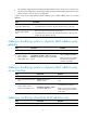
Step 2. Add or modify a blackhole MAC address entry. Command mac-address blackhole mac-address vlan vlan-id Remarks By default, no blackhole MAC address entry is configured. Make sure you have created the VLAN. Disabling MAC address learning on an interface MAC address learning is enabled by default. To prevent the MAC address table from being saturated when the device is experiencing attacks, disable MAC address learning.
To configure the aging timer for dynamic MAC address entries: Step Command Remarks 1. Enter system view. system-view N/A 2. Configure the aging timer for dynamic MAC address entries. mac-address timer { aging seconds | no-aging } The aging timer for dynamic MAC address entries is 300 seconds. Displaying and maintaining the MAC address table Execute display commands in any view. Task Command Display MAC address table information.
# Set the aging timer to 500 seconds for dynamic MAC address entries. [Device] mac-address timer aging 500 Verifying the configuration # Display the static MAC address entries for interface GigabitEthernet 2/1/1. [Device] display mac-address static interface gigabitethernet 2/1/1 MAC Address VLAN ID State Port 000f-e235-dc71 1 Static GE2/1/1 Aging N # Display the blackhole MAC address entries.
Configuring Ethernet link aggregation Ethernet link aggregation bundles multiple physical Ethernet links into one logical link, called an aggregate link. Link aggregation has the following benefits: • Increased bandwidth beyond the limits of any single link. In an aggregate link, traffic is distributed across the member ports. • Improved link reliability. The member ports dynamically back up one another. When a member port fails, its traffic is automatically switched to other member ports.
NOTE: The router supports only Layer 3 link aggregation in the current software version. Aggregation states of member ports in an aggregation group A member port in an aggregation group can be in either of the following aggregation states: • Selected—A Selected port can forward traffic. • Unselected—An Unselected port cannot forward traffic. Operational key When aggregating ports, the system automatically assigns each port an operational key based on port information, such as port rate and duplex mode.
NOTE: The protocol configuration for a member port is effective only when the member port leaves the aggregation group. Link aggregation modes Link aggregation has dynamic and static modes: • Static aggregation mode—Aggregation is stable. The aggregation state of the member ports are not affected by the peer ports. • Dynamic aggregation mode—The peering system automatically maintains the aggregation state of the member ports, which reduces the administrators' workload.
Figure 2 Setting the aggregation state of a member port in a static aggregation group To ensure stable aggregation state and service continuity, do not change the operational key or attribute configurations on any member port. If you need to make this change, make sure you understand its impact on the live network. Any operational key or attribute configuration change might affect the aggregation state of link aggregation member ports and ongoing traffic.
LACP functions Basic LACP functions are implemented through the basic LACPDU fields, including the system LACP priority, system MAC address, port priority, port number, and operational key. LACP operating modes LACP can operate in active or passive mode. When LACP is operating in passive mode on a local member port and its peer port, both ports cannot send LACPDUs. When LACP is operating in active mode on the port on either end of a link, both ports can send LACPDUs.
is chosen. If two ports have the same aggregation priority, the system compares their port numbers. The port with the smaller port number and the same attribute configurations as the aggregate interface becomes the reference port. Setting the aggregation state of each member port After the reference port is chosen, the system with the lower system ID sets the state of each member port in the dynamic aggregation group on its side as shown in Figure 3.
{ None of the full-duplex ports can be chosen as Selected ports. { Only half-duplex ports exist in the group. • To ensure stable aggregation and service continuity, do not change the operational key or attribute configurations on any member port. • When the aggregation state of a local port changes in a dynamic aggregation group, the aggregation state of the peer port also changes.
Configuring a static aggregation group To guarantee a successful static aggregation, make sure that the ports at both ends of each link are in the same aggregation state. Avoid assigning ports to a static aggregation group that has reached the limit on Selected ports. These ports will be placed in Unselected state to avoid traffic interruption on the current Selected ports. However, a device reboot can cause the aggregation state of member ports to change.
Step Command Remarks 3. Create a Layer 3 aggregate interface and enter Layer 3 aggregate interface view. interface route-aggregation interface-number When you create a Layer 3 aggregate interface, the system automatically creates a Layer 3 static aggregation group numbered the same. 4. Configure the aggregation group to operate in dynamic aggregation mode. link-aggregation mode dynamic By default, an aggregation group operates in static aggregation mode. 5. Exit to system view. quit N/A 6.
Step Command Remarks 2. Enter Layer 3 aggregate interface or subinterface view. interface route-aggregation { interface-number | interface-number.subnumber } N/A 3. Configure the description of the aggregate interface or subinterface. description text By default, the description of an interface is in the format of interface-name Interface.
The maximum number of Selected ports allowed in an aggregation group is limited by either the configured maximum number or hardware capability, whichever value is smaller. You can configure backup between two ports by performing the following tasks: • Assign two ports to an aggregation group. • Configure the maximum number of Selected ports allowed in the aggregation group as one.
• When an aggregate interface is brought up, the aggregation state of ports in the corresponding aggregation group is recalculated. To shut down an aggregate interface: Step Command Remarks 1. Enter system view. system-view N/A 2. Enter Layer 3 aggregate interface or subinterface view. interface route-aggregation { interface-number | interface-number.subnumber } N/A 3. Shut down the aggregate interface or subinterface. shutdown By default, all aggregate interfaces are up.
Configuring group-specific load sharing criteria Step Command 1. Enter system view. system-view 2. Enter Layer 3 aggregate interface view. interface route-aggregation interface-number 3. Configure the load sharing criteria for the aggregation group. link-aggregation load-sharing mode { destination-ip | destination-port | source-ip | source-port } Enabling link-aggregation traffic redirection Link-aggregation traffic redirection prevents traffic interruption.
Task Command Display the local system ID. display lacp system-id Display the global or group-specific link-aggregation load sharing criteria. display link-aggregation load-sharing mode [ interface [ route-aggregation interface-number ] ] Display detailed link aggregation information for link aggregation member ports. display link-aggregation member-port [ interface-list ] Display summary information about all aggregation groups.
[DeviceA-GigabitEthernet2/1/2] port link-aggregation group 1 [DeviceA-GigabitEthernet2/1/2] quit [DeviceA] interface gigabitethernet 2/1/3 [DeviceA-GigabitEthernet2/1/3] port link-aggregation group 1 [DeviceA-GigabitEthernet2/1/3] quit 2. Configure Device B in the same way Device A is configured. Verifying the configuration # Display detailed information about all aggregation groups on Device A.
# Configure the link aggregation mode as dynamic. [DeviceA-Route-Aggregation1] link-aggregation mode dynamic # Configure an IP address and subnet mask for Route-Aggregation 1. [DeviceA-Route-Aggregation1] ip address 192.168.1.1 24 [DeviceA-Route-Aggregation1] quit # Assign Layer 3 Ethernet interfaces GigabitEthernet 2/1/1 through GigabitEthernet 2/1/3 to aggregation group 1.
Layer 3 aggregation load sharing configuration example Network requirements As shown in Figure 6: • Configure Layer 3 static aggregation groups 1 and 2 on Device A and Device B, respectively. • Configure IP addresses and subnet masks for the corresponding Layer 3 aggregate interfaces. • Configure link aggregation group 1 to perform load sharing based on source IP address. • Configure link aggregation group 2 to perform load sharing based on destination IP address.
[DeviceA] interface gigabitethernet 2/1/3 [DeviceA-GigabitEthernet2/1/3] port link-aggregation group 2 [DeviceA-GigabitEthernet2/1/3] quit [DeviceA] interface gigabitethernet 2/1/4 [DeviceA-GigabitEthernet2/1/4] port link-aggregation group 2 [DeviceA-GigabitEthernet2/1/4] quit 2. Configure Device B in the same way Device A is configured. Verifying the configuration # Display detailed information about all aggregation groups on Device A.
Configuring port isolation In this chapter, "MSR2000" refers to MSR2003. "MSR3000" collectively refers to MSR3012, MSR3024, MSR3044, MSR3064. "MSR4000" collectively refers to MSR4060 and MSR4080. Overview The port isolation feature isolates Layer 2 traffic for data privacy and security without using VLANs. Ports in an isolation group cannot communicate with each other. However, they can communicate with ports outside the isolation group.
Assigning a port to the isolation group The router supports only one isolation group that is automatically created as isolation group 1. You cannot delete the isolation group or create other isolation groups on the router. The number of ports assigned to the isolation group is not limited. To assign a port to the isolation group: Step Command Remarks 1. Enter system view. system-view N/A 2. Enter Layer 2 Ethernet interface view.
Figure 8 Network diagram Configuration procedure # Assign ports GigabitEthernet 2/1/1, GigabitEthernet 2/1/2, and GigabitEthernet 2/1/3 to the isolation group.
Configuring spanning tree protocols Spanning tree protocols eliminate loops in a physical link-redundant network by selectively blocking redundant links and putting them in a standby state. The recent versions of STP include the Rapid Spanning Tree Protocol (RSTP), the Per-VLAN Spanning Tree (PVST), and the Multiple Spanning Tree Protocol (MSTP). In this chapter, "MSR2000" refers to MSR2003. "MSR3000" collectively refers to MSR3012, MSR3024, MSR3044, MSR3064.
Basic concepts in STP Root bridge A tree network must have a root bridge. The entire network contains only one root bridge, and all the other bridges in the network are called leaf nodes. The root bridge is not permanent, but can change with changes of the network topology. Upon initialization of a network, each device generates and periodically sends configuration BPDUs, with itself as the root bridge. After network convergence, only the root bridge generates and periodically sends configuration BPDUs.
Path cost Path cost is a reference value used for link selection in STP. To prune the network into a loop-free tree, STP calculates path costs to select the most robust links and block redundant links that are less robust. Calculation process of the STP algorithm The spanning tree calculation process described in the following sections is a simplified process for example only. Calculation process The STP algorithm uses the following calculation process: 1. Network initialization.
Table 3 Selecting the optimum configuration BPDU Step Actions Upon receiving a configuration BPDU on a port, the device compares the priority of the received configuration BPDU with that of the configuration BPDU generated by the port: • If the former priority is lower, the device discards the received configuration BPDU and 1 keeps the configuration BPDU the port generated.
In Table 4, each configuration BPDU contains the following fields: root bridge ID, root path cost, designated bridge ID, and designated port ID. Table 4 Initial state of each device Device Device A Device B Device C 2. Port name Configuration BPDU on the port Port A1 {0, 0, 0, Port A1} Port A2 {0, 0, 0, Port A2} Port B1 {1, 0, 1, Port B1} Port B2 {1, 0, 1, Port B2} Port C1 {2, 0, 2, Port C1} Port C2 {2, 0, 2, Port C2} Configuration BPDUs comparison on each device.
Device Configuration BPDU on ports after comparison Comparison process Port B1 performs the following tasks: 10. Receives the configuration BPDU of Port A1 {0, 0, 0, Port A1}. 11. Determines that the received configuration BPDU is superior to its existing configuration BPDU {1, 0, 1, Port B1}. 12. Updates its configuration BPDU. Port B2 performs the following tasks: 13. Receives the configuration BPDU of Port C2 {2, 0, 2, Port C2}. • Port B1: {0, 0, 0, Port A1} • Port B2: {1, 0, 1, Port B2} 14.
Device Configuration BPDU on ports after comparison Comparison process Device C performs the following tasks: 25. Compares the configuration BPDUs of all its ports. 26. Decides that the configuration BPDU of Port C1 is the optimum. 27. Selects Port C1 as the root port with the configuration BPDU unchanged. Based on the configuration BPDU and path cost of the root port, Device C calculates the configuration BPDU of Port C2 {0, 10, 2, Port C2}.
After the comparison processes described in Table 5, a spanning tree with Device A as the root bridge is established, as shown in Figure 11. Figure 11 The final calculated spanning tree The configuration BPDU forwarding mechanism of STP The configuration BPDUs of STP are forwarded according to these guidelines: • Upon network initiation, every device regards itself as the root bridge and generates configuration BPDUs with itself as the root.
• Hello time The device sends hello packets at the hello time interval to the neighboring devices to make sure the paths are fault-free. • Max age The device uses the max age to determine whether a stored configuration BPDU has expired and discards it if the max age is exceeded. RSTP RSTP achieves rapid network convergence by allowing a newly elected root port or designated port to enter the forwarding state much faster than STP.
permits too many VLANs, both resources and calculations for maintaining the VLAN spanning trees increase dramatically. If a status change occurs to the trunk or hybrid port that permits multiple VLANs, the device CPU will be overburdened with recalculating the affected spanning trees. As a result, network performance is degraded. MSTP features Developed based on IEEE 802.1s, MSTP overcomes the limitations of STP, RSTP, and PVST.
Figure 12 Basic concepts in MSTP VLAN 1 MSTI 1 MSTI 2 VLAN 2 MSTI 0 Other VLANs VLAN 1 MSTI 1 MSTI 2 VLAN 2 MSTI 0 Other VLANs MST region 1 MST region 4 MST region 2 MST region 3 VLAN 1 MSTI 1 MSTI 2 VLAN 2 MSTI 0 Other VLANs CST VLAN 1 MSTI 1 MSTI 2 VLAN 2&3 MSTI 0 Other VLANs Figure 13 Network diagram and topology of MST region 3 MST region A multiple spanning tree region (MST region) consists of multiple devices in a switched network and the network segments among them.
• Same VLAN-to-instance mapping configuration • Same MSTP revision level • Physically linked together Multiple MST regions can exist in a switched network. You can assign multiple devices to the same MST region. In Figure 12: • The switched network comprises four MST regions, MST region 1 through MST region 4. • All devices in each MST region have the same MST region configuration.
• The regional root of MSTI 2 is Device C. • The regional root of MSTI 0 (also known as the IST) is Device A. Common root bridge The common root bridge is the root bridge of the CIST. In Figure 12, the common root bridge is a device in MST region 1. Port roles A port can play different roles in different MSTIs. As shown in Figure 14, an MST region comprises Device A, Device B, Device C, and Device D. Port A1 and port A2 of Device A connect to the common root bridge.
• Master port—Serves as a port on the shortest path from the local MST region to the common root bridge. The master port is not always located on the regional root. It is a root port on the IST or CIST and still a master port on the other MSTIs. • Boundary port—Connects an MST region to another MST region or to an STP/RSTP-running device. In MSTP calculation, a boundary port's role on an MSTI is consistent with its role on the CIST. However, that is not true with master ports.
MSTI calculation Within an MST region, MSTP generates different MSTIs for different VLANs based on the VLAN-to-instance mappings. For each spanning tree, MSTP performs a separate calculation process similar to spanning tree calculation in STP. For more information, see "Calculation process of the STP algorithm." In MSTP, a VLAN packet is forwarded along the following paths: • Within an MST region, the packet is forwarded along the corresponding MSTI.
Plan the device roles (the root bridge or leaf node). • STP configuration task list Tasks at a glance Configuring the root bridge: • • • • • • • • • (Required.) Setting the spanning tree mode (Optional.) Configuring the root bridge or a secondary root bridge (Optional.) Configuring the device priority (Optional.) Configuring the network diameter of a switched network (Optional.) Configuring spanning tree timers (Optional.) Configuring the timeout factor (Optional.
Tasks at a glance Configuring the leaf nodes: • • • • • • • • • • (Required.) Setting the spanning tree mode (Optional.) Configuring the device priority (Optional.) Configuring the timeout factor (Optional.) Configuring the BPDU transmission rate (Optional.) Configuring edge ports (Optional.) Configuring path costs of ports (Optional.) Configuring the port priority (Optional.) Configuring the port link type (Optional.) Enabling outputting port state transition information (Required.
MSTP configuration task list Tasks at a glance Configuring the root bridge: • • • • • • • • • • • • • • (Required.) Setting the spanning tree mode (Required.) Configuring an MST region (Optional.) Configuring the root bridge or a secondary root bridge (Optional.) Configuring the device priority (Optional.) Configuring the maximum hops of an MST region (Optional.) Configuring the network diameter of a switched network (Optional.) Configuring spanning tree timers (Optional.
• PVST mode—All ports of the device send PVST BPDUs. Each VLAN maintains a spanning tree. In a network, the amount of spanning trees maintained by all devices equals the number of PVST-enabled VLANs multiplied by the number of PVST-enabled ports. If the amount of spanning trees exceeds the capacity of the network, device CPUs will be overloaded. Packet forwarding is interrupted, and the network becomes unstable. • MSTP mode—All ports of the device send MSTP BPDUs.
instability, the MST region configuration takes effect only after you activate it by doing one of the following: • Use the active region-configuration command. • Enable a spanning tree protocol by using the stp global enable command if the spanning tree protocol is disabled. In STP, RSTP, or PVST mode, MST region configurations do not take effect. To configure an MST region: Step Command Remarks 1. Enter system view. system-view N/A 2. Enter MST region view.
You can configure the current device as the root bridge by setting the device priority to 0. For the device priority configuration, see "Configuring the device priority." Configuring the current device as the root bridge of a specific spanning tree Step Command Remarks 1. Enter system view. system-view N/A • In STP/RSTP mode: stp root primary 2. Configure the current device as the root bridge.
Step Command Remarks • In STP/RSTP mode: stp priority priority 2. Configure the priority of the current device. • In PVST mode: stp vlan vlan-id-list priority priority The default setting is 32768. • In MSTP mode: stp [ instance instance-list ] priority priority Configuring the maximum hops of an MST region Restrict the region size by setting the maximum hops of an MST region. The hop limit configured on the regional root bridge is used as the hop limit for the MST region.
In PVST mode, the configured network diameter takes effect only on the root bridges of the specified VLANs. To configure the network diameter of a switched network: Step Command Remarks 1. Enter system view. system-view N/A • In STP/RSTP/MSTP mode: 2. Configure the network diameter of the switched network. stp bridge-diameter diameter • In PVST mode: The default setting is 7.
short, the device frequently sends the same configuration BPDUs, which wastes device and network resources. HP recommends that you use the automatically calculated value. • If the max age timer is too short, the device frequently begins spanning tree calculations and might mistake network congestion as a link failure. If the max age timer is too long, the device might fail to promptly detect link failures and quickly launch spanning tree calculations, reducing the auto-sensing capability of the network.
Step Command Remarks 2. Configure the timeout factor of the device. stp timer-factor factor The default setting is 3. Configuring the BPDU transmission rate The maximum number of BPDUs a port can send within each hello time equals the BPDU transmission rate plus the hello timer value. Configure an appropriate BPDU transmission rate based on the physical status of the port and the network structure.
Step Command Remarks 2. Enter Layer 2 Ethernet interface view. interface interface-type interface-number N/A 3. Configure the current ports as edge ports. stp edged-port By default, all ports are non-edge ports. Configuring path costs of ports Path cost is a parameter related to the rate of a port. On a spanning tree device, a port can have different path costs in different MSTIs.
Step Command Remarks 2. Specify a standard for the device to use when it calculates the default path costs of its ports. stp pathcost-standard { dot1d-1998 | dot1t | legacy } By default, the standard used by the device is legacy. Table 7 Mappings between the link speed and the path cost Path cost Link speed Port type IEEE 802.1d-1998 IEEE 802.
Path cost Link speed 20 Gbps 40 Gbps 100 Gbps Port type IEEE 802.1d-1998 IEEE 802.
Step Command Remarks 1. Enter system view. system-view N/A 2. Enter Layer 2 Ethernet interface view. interface interface-type interface-number N/A • In STP/RSTP mode: stp cost cost 3. Configure the path cost of the ports. • In PVST mode: stp vlan vlan-id-list cost cost • In MSTP mode: By default, the system automatically calculates the path cost of each port.
Step Command Remarks 1. Enter system view. system-view N/A interface interface-type interface-number N/A 2. Enter Layer 2 interface view. Ethernet • In STP/RSTP mode: stp port priority priority 3. Configure the port priority. • In PVST mode: stp vlan vlan-id-list port priority priority • In MSTP mode: The default setting is 128 for all ports. stp [ instance instance-list ] port priority priority Configuring the port link type A point-to-point link directly connects two devices.
By default, the packet format recognition mode of a port is auto. The port automatically distinguishes the two MSTP packet formats, and determines the format of packets that it will send based on the recognized format. You can configure the MSTP packet format on a port. Then, the port sends only MSTP packets of the configured format to communicate with devices that send packets of the same format. A port in auto mode sends 802.1s MSTP packets by default.
Enabling the spanning tree feature in STP/RSTP/MSTP mode Step Command Remarks 1. Enter system view. system-view N/A stp global enable By default, the spanning tree feature is disabled globally. 3. Enter Layer 2 Ethernet interface view. interface interface-type interface-number N/A 4. (Optional.) Enable the spanning tree feature for the port. stp enable By default, the spanning tree feature is enabled on all ports. 2. Enable the feature.
Configuration procedure Performing mCheck globally Step Command 1. Enter system view. system-view 2. Perform mCheck. stp global mcheck Performing mCheck in interface view Step Command 1. Enter system view. system-view 2. Enter Layer 2 Ethernet interface view. interface interface-type interface-number 3. Perform mCheck. stp mcheck Configuring Digest Snooping As defined in IEEE 802.
• To make Digest Snooping take effect, you must enable Digest Snooping both globally and on associated ports. HP recommends that you enable Digest Snooping on all associated ports first and then enable it globally. This will make the configuration take effect on all configured ports and reduce impact on the network. • To prevent loops, do not enable Digest Snooping on MST region edge ports. • HP recommends that you enable Digest Snooping first and then the spanning tree feature.
Figure 15 Network diagram MST region Device C Root bridge GE2/1/1 Root port GE2/1/2 Designated port Blocked port Normal link GE2/1/1 GE2/1/1 GE2/1/2 Device A Blocked link GE2/1/2 Device B Configuration procedure # Enable Digest Snooping on GigabitEthernet 2/1/1 of Device A and enable global Digest Snooping on Device A.
Figure 16 Rapid state transition of an MSTP designated port Upstream device Downstream device (1) Proposal for rapid transition The root port blocks non-edge ports. The root port changes to the forwarding state and sends an Agreement to the upstream device. (2) Agreement (3) Agreement The designated port changes to the forwarding state.
Configuration procedure Enable the No Agreement Check feature on the root port. To configure No Agreement Check: Step Command Remarks 1. Enter system view. system-view N/A interface interface-type interface-number N/A stp no-agreement-check By default, No Agreement Check is disabled. 2. Enter Layer 2 interface view. 3. Enable Check.
Enabling BPDU guard For access layer devices, the access ports can directly connect to the user terminals (such as PCs) or file servers. The access ports are configured as edge ports to allow rapid transition. When these ports receive configuration BPDUs, the system automatically sets the ports as non-edge ports and starts a new spanning tree calculation process. This causes a change of network topology. Under normal conditions, these ports should not receive configuration BPDUs.
Step Command Remarks 1. Enter system view. system-view N/A interface interface-type interface-number N/A stp root-protection By default, root guard is disabled. 2. Enter Layer 2 interface view. 3. Enable the function. root Ethernet guard Enabling loop guard By continuing to receive BPDUs from the upstream device, a device can maintain the state of the root port and blocked ports.
To configure port role restriction: Step Command Remarks 1. Enter system view. system-view N/A 2. Enter Layer 2 Ethernet interface view. interface interface-type interface-number N/A 3. Enable port role restriction. stp role-restriction By default, port role restriction is disabled. Configuring TC-BPDU transmission restriction CAUTION: Enabling TC-BPDU transmission restriction on a port might cause the previous forwarding address table to fail to be updated when the topology changes.
Step Command Remarks 2. Enable the TC-BPDU guard function. stp tc-protection 3. (Optional.) Configure the maximum number of forwarding address entry flushes that the device can perform every 10 seconds. stp tc-protection threshold number By default, TC-BPDU guard is enabled. HP recommends not disabling this feature. The default setting is 6. Displaying and maintaining the spanning tree Execute display commands in any view and reset command in user view.
Spanning tree configuration example MSTP configuration example Network requirements As shown in Figure 19, all devices on the network are in the same MST region. Device A and Device B work at the distribution layer. Device C and Device D work at the access layer. Configure MSTP so that packets of different VLANs are forwarded along different spanning trees: • VLAN 10 packets are forwarded along MSTI 1. • VLAN 30 packets are forwarded along MSTI 3. • VLAN 40 packets are forwarded along MSTI 4.
# Map VLAN 10, VLAN 30, and VLAN 40 to MSTI 1, MSTI 3, and MSTI 4, respectively. [DeviceA-mst-region] instance 1 vlan 10 [DeviceA-mst-region] instance 3 vlan 30 [DeviceA-mst-region] instance 4 vlan 40 # Configure the revision level of the MST region as 0. [DeviceA-mst-region] revision-level 0 # Activate MST region configuration. [DeviceA-mst-region] active region-configuration [DeviceA-mst-region] quit # Configure the current device as the root bridge of MSTI 1.
# Configure the current device as the root bridge of MSTI 4. [DeviceC] stp instance 4 root primary # Enable the spanning tree feature globally. [DeviceC] stp global enable 5. Configure Device D: # Enter MST region view, and configure the MST region name as example. system-view [DeviceD] stp region-configuration [DeviceD-mst-region] region-name example # Map VLAN 10, VLAN 30, and VLAN 40 to MSTI 1, MSTI 3, and MSTI 4, respectively.
3 GigabitEthernet2/1/3 DESI FORWARDING NONE # Display brief spanning tree information on Device C.
• Device C and Device D work at the access layer. Configure PVST to meet the following requirements: • Packets of VLAN 10, VLAN 20, VLAN 30, and VLAN 40 are forwarded along the spanning trees of VLAN 10, VLAN 20, VLAN 30, and VLAN 40. • VLAN 10, VLAN 20, and VLAN 30 are terminated on the distribution layer devices, and VLAN 40 is terminated on the access layer devices. • The root bridge of VLAN 10 and VLAN 20 as Device A. • The root bridge of VLAN 30 as Device B.
[DeviceB] stp vlan 30 root primary # Enable the spanning tree feature globally and in VLAN 10, VLAN 20, and VLAN 30. [DeviceB] stp global enable [DeviceB] stp vlan 10 20 30 enable 4. Configure Device C: # Set the spanning tree mode to PVST. system-view [DeviceC] stp mode pvst # Configure the device as the root bridge of VLAN 40. [DeviceC] stp vlan 40 root primary # Enable the spanning tree feature globally and in VLAN 10, VLAN 20, and VLAN 40.
VLAN ID Port Role STP State Protection 10 GigabitEthernet2/1/1 ROOT FORWARDING NONE 10 GigabitEthernet2/1/2 ALTE DISCARDING NONE 20 GigabitEthernet2/1/1 ROOT FORWARDING NONE 20 GigabitEthernet2/1/2 ALTE DISCARDING NONE 20 GigabitEthernet2/1/3 DESI FORWARDING NONE 40 GigabitEthernet2/1/3 DESI FORWARDING NONE # Display brief spanning tree information on Device D.
Configuring loop detection Overview Incorrect network connections or configurations can create Layer 2 loops, which results in repeated transmission of broadcasts, multicasts, or unknown unicasts. The repeated transmission can waste network resources and can sometimes paralyze networks. The loop detection mechanism immediately generates a log when a loop occurs so that you are promptly notified to adjust network connections and configurations. You can configure loop detection to shut down the looped port.
The inner frame header for loop detection contains the following fields: • Code—Protocol sub-type, which is 0x0001, indicating the loop detection protocol. • Version—Protocol version, which is always 0x0000. • Length—Length of the frame. The value includes the inner header, but excludes the Ethernet header. • Reserved—This field is reserved. Frames for loop detection are encapsulated as TLV triplets. Table 8 TLVs supported by loop detection TLV Description Remarks End of PDU End of a PDU.
1. The router automatically shuts down the port. 2. The router automatically sets the port to the forwarding state after the detection timer configured by using the shutdown-interval command expires. For more information about the shutdown-interval command, see Fundamentals Command Reference. 3. The router shuts down the port again if a loop is still detected on the port when the detection timer expires. This process is repeated until the loop is removed.
Configuring the loop protection action You can configure the loop protection action globally or on a per-port basis. The global configuration applies to all ports. The per-port configuration applies to the individual ports. The per-port configuration takes precedence over the global configuration. Configuring the global loop protection action Step Command Remarks 1. Enter system view. system-view N/A 2. Configure the global loop protection action.
Task Command Display the loop detection configuration and status. display loopback-detection Loop detection configuration example Network requirements As shown in Figure 25, configure loop detection on Router A, so that Router A generates a log as a notification and automatically shuts down the port on which a loop is detected. Figure 25 Network diagram Router A GE2/1/1 GE2/1/2 Router B Router C VLAN 100 Configuration procedure 1.
# Configure the global loop protection action as shutdown. [RouterA] loopback-detection global action shutdown # Set the loop detection interval to 35 seconds. [RouterA] loopback-detection interval-time 35 2. Configure Router B: # Create VLAN 100. system-view [RouterB] vlan 100 [RouterB–vlan100] quit # Configure GigabitEthernet 2/1/1 and GigabitEthernet 2/1/2 as trunk ports, and assign them to VLAN 100.
The output shows the following information: • Router A detects loops on ports GigabitEthernet 2/1/1 and GigabitEthernet 2/1/2 within a loop detection interval. • Router A automatically shuts down the ports and generates log messages. # Use the display loopback-detection command to display the loop detection configuration and status on routers, for example, Router A. [RouterA] display loopback-detection Loop detection is enabled. Loop detection interval is 35 second(s). No loopback is detected.
Configuring VLANs This chapter provides an overview of VLANs and explains how to configure them. Overview Ethernet is a family of shared-media LAN technologies based on the CSMA/CD mechanism. An Ethernet LAN is both a collision domain and a broadcast domain. Because the medium is shared, collisions and broadcasts are common in an Ethernet LAN. Typically, bridges and Layer 2 switches can reduce collisions in an Ethernet LAN.
Figure 27 VLAN tag placement and format A VLAN tag includes the following fields: • TPID—16-bit tag protocol identifier that indicates whether a frame is VLAN-tagged. By default, the TPID value is 0x8100, indicating that the frame is VLAN-tagged. However, device vendors can set TPID to different values. For compatibility with neighbor devices, configure the TPID value on the device to be the same as the neighbor device. • Priority—3-bit long 802.1p priority of the frame.
Step Command Remarks 3. Enter VLAN view. vlan vlan-id To configure a VLAN after you create a list of VLANs, you must perform this step. 4. Configure a name for the VLAN. name text By default, VLAN names are in the format VLAN vlan-id. For example, the name of VLAN 100 is VLAN 0100 by default. description text The default setting is VLAN vlan-id, which is the ID of the VLAN. For example, the description of VLAN 100 is VLAN 0100 by default. 5. Configure the description of the VLAN.
Step Command Remarks 8. (Optional.) Restore the default settings for the VLAN interface. default N/A 9. (Optional.) Bring up the VLAN interface. undo shutdown By default, a VLAN interface is up. Configuring port-based VLANs Introduction Port-based VLANs group VLAN members by port. A port forwards packets from a VLAN only after it is assigned to the VLAN. Port link type You can configure the link type of a port as access, trunk, or hybrid.
How ports of different link types handle frames Actions Access In the inbound direction for an untagged frame Tags the frame with the PVID tag. In the inbound direction for a tagged frame Trunk Hybrid • If the PVID is permitted on the port, tags the frame with the PVID tag. • If not, drops the frame. • Receives the frame if its VLAN ID is the same as the PVID. • Drops the frame if its VLAN ID is different from the PVID. • Receives the frame if its VLAN is permitted on the port.
Assigning a trunk port to a VLAN A trunk port can allow multiple VLANs. You can assign it to a VLAN in interface view. When you assign a trunk port to a VLAN, follow these restrictions and guidelines: • To change the link type of a port from trunk to hybrid or vice versa, set the link type to access first. • You must configure the trunk port to allow packets from the PVID to pass through by using the port trunk permit vlan command.
Configuring a VLAN group A VLAN group includes a set of VLANs. You can add multiple VLAN lists to a VLAN group. You can configure the authentication server to assign VLANs in a VLAN group to an 802.1X user that has passed authentication. For more information about 802.1X authentication, see Security Configuration Guide. To configure a VLAN group: Step Command Remarks 1. Enter system view. system-view N/A 2. Create a VLAN group and enter VLAN group view.
Figure 28 Network diagram Configuration procedure 1. Configure Router A: # Create VLAN 100, and assign GigabitEthernet 2/1/1 to VLAN 100. system-view [RouterA] vlan 100 [RouterA-vlan100] port gigabitethernet 2/1/1 [RouterA-vlan100] quit # Create VLAN 200, and assign GigabitEthernet 2/1/2 to VLAN 200. [RouterA] vlan 200 [RouterA-vlan200] port gigabitethernet 2/1/2 [RouterA-vlan200] quit # Configure GigabitEthernet 2/1/3 as a trunk port to forward packets from VLANs 100 and 200 to Device B.
Untagged ports: GigabitEthernet2/1/1 [RouterA-GigabitEthernet2/1/3] display vlan 200 VLAN ID: 200 VLAN type: Static Route interface: Not configured Description: VLAN 0200 Name: VLAN 0200 Tagged ports: GigabitEthernet2/1/3 Untagged ports: GigabitEthernet2/1/2 96
Configuring QinQ This document uses the following terms: • CVLAN—Customer network VLANs, also called "inner VLANs," refer to VLANs that a customer uses on the private network. • SVLAN—Service provider network VLANs, also called "outer VLANs," refer to VLANs that a service provider uses to transmit VLAN tagged traffic for customers. Overview 802.1Q-in-802.1Q (QinQ) enables service providers to extend Layer 2 Ethernet connections across a MAN between two customer sites.
The devices in the service provider network forward a tagged frame according to its SVLAN tag only. The CVLAN tag is transmitted as part of the frame's payload.
Feature and hardware compatibility QinQ is supported only on the HMIM 24GSW, HMIM 24GSW-PoE, and HMIM 8GSW interface modules. Restrictions and guidelines The inner 802.1Q tag of QinQ frames is treated as part of payload. For correct transmission of QinQ frames, HP recommends that you set the MTU of each interface to a minimum of 1504 bytes on the service provider network. This value is the sum of the default Ethernet interface MTU (1500 bytes) and a VLAN tag's size (4 bytes).
Table 9 Reserved EtherType values Protocol type Value ARP 0x0806 PUP 0x0200 RARP 0x8035 IP 0x0800 IPv6 0x86DD PPPoE 0x8863/0x8864 MPLS 0x8847/0x8848 IPX/SPX 0x8137 IS-IS 0x8000 LACP 0x8809 LLDP 0x88CC 802.1X 0x888E 802.1ag 0x8902 Cluster 0x88A7 Reserved 0xFFFD/0xFFFE/0xFFFF Configuring the CVLAN TPID value Step Command Remarks 1. Enter system view. system-view N/A 2. Set the CVLAN TPID. qinq ethernet-type customer-tag hex-value The default setting is 0x8100.
Setting the 802.1p priority in SVLAN tags By default, the 802.1p priority in the SVLAN tag added by a QinQ-enabled port depends on the priority trust mode on the port. • If the 802.1p priority in frames is trusted, the device copies the 802.1p priority in the CVLAN tag to the SVLAN tag. • If port priority is trusted, the port priority (0 by default) is used as the 802.1p priority in the SVLAN tag. To set the 802.1p priority in SVLAN tags: Step Command Remarks 1. Enter system view.
Displaying and maintaining QinQ Execute the display command in any view. Task Command Display QinQ-enabled ports. display qinq [ interface interface-type interface-number ] QinQ configuration example Network requirements As shown in Figure 31: • The service provider assigns VLAN 100 to Company A's VLANs 10 through 70. • The service provider assigns VLAN 200 to Company B's VLANs 30 through 90. • The devices between PE 1 and PE 2 in the service provider network use a TPID value of 0x8200.
# Configure the port as a trunk port, and assign it to VLAN 100 and VLANs 10 through 70. system-view [PE1] interface gigabitethernet 2/1/1 [PE1-GigabitEthernet2/1/1] port link-type trunk [PE1-GigabitEthernet2/1/1] port trunk permit vlan 100 10 to 70 # Configure VLAN 100 as the PVID for the port. [PE1-GigabitEthernet2/1/1] port trunk pvid vlan 100 # Enable QinQ on the port. [PE1-GigabitEthernet2/1/1] qinq enable [PE1-GigabitEthernet2/1/1] quit 2.
[PE2-GigabitEthernet2/1/2] port trunk permit vlan 100 200 # Set the TPID value in the SVLAN tags to 0x8200 on the port. [PE2-GigabitEthernet2/1/2] qinq ethernet-type service-tag 8200 [PE2-GigabitEthernet2/1/2] quit 3. Configure GigabitEthernet 2/1/3: # Configure the port as a trunk port, and assign it to VLAN 100 and VLANs 10 through 70.
Configuring LLDP Overview In a heterogeneous network, a standard configuration exchange platform ensures that different types of network devices from different vendors can discover one another and exchange configuration. The Link Layer Discovery Protocol (LLDP) is specified in IEEE 802.1AB. The protocol operates on the data link layer to exchange device information between directly connected devices.
Figure 32 LLDP neighbor relationships LLDP frame formats LLDP sends device information in LLDP frames. LLDP frames are encapsulated in Ethernet II or SNAP frames. • LLDP frame encapsulated in Ethernet II Figure 33 Ethernet II-encapsulated LLDP frame Table 10 Fields in an Ethernet II-encapsulated LLDP frame Field Destination MAC address Description MAC address to which the LLDP frame is advertised.
Field Description FCS Frame check sequence, a 32-bit CRC value used to determine the validity of the received Ethernet frame. LLDP frame encapsulated in SNAP • Figure 34 SNAP-encapsulated LLDP frame Table 11 Fields in a SNAP-encapsulated LLDP frame Field Description Destination MAC address MAC address to which the LLDP frame is advertised. It is the same as that for Ethernet II-encapsulated LLDP frames. Source MAC address MAC address of the sending port.
• LLDP-MED (media endpoint discovery) TLVs Basic management TLVs are essential to device management. Organizationally specific TLVs and LLDP-MED TLVs are used for enhanced device management. They are defined by standardization or other organizations and are optional to LLDPDUs. • Basic management TLVs Table 12 lists the basic management TLV types. Some of them are mandatory to LLDPDUs. Table 12 Basic management TLVs Type Description Chassis ID Specifies the bridge MAC address of the sending device.
Type Description PFC Priority-based Flow Control. APP Application protocol. NOTE: • HP devices support only receiving protocol identity TLVs and VID usage digest TLVs. • Layer 3 Ethernet ports support only link aggregation TLVs. • IEEE 802.3 organizationally specific TLVs Table 14 IEEE 802.
Table 15 LLDP-MED TLVs Type Description LLDP-MED Capabilities Allows a network device to advertise the LLDP-MED TLVs that it supports. Network Policy Allows a network device or terminal device to advertise the VLAN ID of a port, the VLAN type, and the Layer 2 and Layer 3 priorities for specific applications. Extended Power-via-MDI Allows a network device or terminal device to advertise power supply capability. This TLV is an extension of the Power Via MDI TLV.
Each time the LLDP operating mode of an LLDP agent changes, its LLDP protocol state machine reinitializes. A configurable reinitialization delay prevents frequent initializations caused by frequent changes to the operating mode. If you configure the reinitialization delay, an LLDP agent must wait the specified amount of time to initialize LLDP after the LLDP operating mode changes.
LLDP configuration task list Tasks at a glance Performing basic LLDP configuration: • • • • • • • • • (Required.) Enabling LLDP (Optional.) Configuring the LLDP bridge mode (Optional.) Setting the LLDP operating mode (Optional.) Setting the LLDP reinitialization delay (Optional.) Enabling LLDP polling (Optional.) Configuring the advertisable TLVs (Optional.) Configuring the management address and its encoding format (Optional.) Setting other LLDP parameters (Optional.
• Customer bridge mode—In customer bridge mode, LLDP supports nearest bridge agents, nearest non-TPMR bridge agents, and nearest customer bridge agents. LLDP processes the LLDP frames with destination MAC addresses for these agents and transparently transmits the LLDP frames with other destination MAC addresses in the VLAN. To configure the LLDP bridge mode: Step Command Remarks 1. Enter system view. system-view N/A 2. Configure LLDP to operate in service bridge mode.
Step Command Remarks 1. Enter system view. system-view N/A 2. Set the LLDP reinitialization delay. lldp timer reinit-delay delay The default setting is 2 seconds. Enabling LLDP polling With LLDP polling enabled, a device periodically searches for local configuration changes. When the device detects a configuration change, it sends LLDP frames to inform neighboring devices of the change. To enable LLDP polling: Step Command Remarks 1. Enter system view. system-view N/A 2.
Step Command Remarks 3. Configure the advertisable TLVs (in Layer 2 Ethernet interface view).
By default, management addresses are encoded in numeric format. If a neighbor encodes its management address in string format, configure the encoding format of the management address as string on the connecting port. This guarantees normal communication with the neighbor. To configure a management address to be advertised and its encoding format on a port: Step Command Remarks 1. Enter system view. system-view N/A 2. Enter Layer 2/Layer 3 Ethernet interface view, or Layer 3 aggregate interface view.
Step Command Remarks 1. Enter system view. system-view N/A 2. Set the TTL multiplier. lldp hold-multiplier value The default setting is 4. 3. Set the LLDP frame transmission interval. lldp timer tx-interval interval The default setting is 30 seconds. 4. Set the token bucket size for sending LLDP frames. lldp max-credit credit-value The default setting is 5. 5. Set the LLDP frame transmit delay. lldp timer tx-delay delay The default setting is 2 seconds. 6.
• Enable LLDP on the port connecting to an IP phone. • Configure LLDP to operate in TxRx mode on the port. Configuration procedure CDP-compatible LLDP operates in one of the following modes: • TxRx—CDP packets can be transmitted and received. • Disable—CDP packets cannot be transmitted or received. LLDP traps are sent periodically, and the interval is configurable. To make CDP-compatible LLDP take effect on a ports, follow these steps: • Enable CDP-compatible LLDP globally.
Step Command Remarks • In Layer 2 Ethernet interface view: lldp notification remote-change enable • In Layer 3 Ethernet interface view: lldp [ agent { nearest-customer | nearest-nontpmr } ] notification remote-change enable 3. Enable LLDP trapping. By default, LLDP trapping is disabled. • In Layer 3 aggregate interface view: lldp agent { nearest-customer | nearest-nontpmr } notification remote-change enable 4. Enable LLDP-MED trapping (in Layer 2/Layer 3 Ethernet interface view).
• An MED device and Router B are connected to GigabitEthernet 2/1/1 and GigabitEthernet 2/1/2 of Router A, respectively. Enable LLDP globally on Router A and Router B to perform the following tasks: • Monitor the link between Router A and Router B on the NMS. • Monitor the link between Router A and the MED device on the NMS. Figure 36 Network diagram Configuration procedure 1. Configure Router A: # Enable LLDP globally.
Verifying the configuration # Verify the following items: • GigabitEthernet 2/1/1 of Router A connects to a MED device. • GigabitEthernet 2/1/2 of Router A connects to a non-MED device. • Both ports operate in Rx mode, and they can receive LLDP frames but cannot send LLDP frames.
Admin status : RX_Only Trap flag : No MED trap flag : No Polling interval : 0s Number of LLDP neighbors : 1 Number of MED neighbors : 0 Number of CDP neighbors : 0 Number of sent optional TLV : 21 Number of received unknown TLV : 3 LLDP agent nearest-nontpmr: Port status of LLDP : Enable Admin status : Disable Trap flag : No MED trap flag : No Polling interval : 0s Number of LLDP neighbors : 0 Number of MED neighbors : 0 Number of CDP neighbors : 0 Number of sent optional TL
LLDP status information of port 1 [GigabitEthernet2/1/1]: LLDP agent nearest-bridge: Port status of LLDP : Enable Admin status : RX_Only Trap flag : No MED trap flag : No Polling interval : 0s Number of LLDP neighbors : 1 Number of MED neighbors : 1 Number of CDP neighbors : 0 Number of sent optional TLV : 0 Number of received unknown TLV : 5 LLDP agent nearest-nontpmr: Port status of LLDP : Enable Admin status : Disable Trap flag : No MED trap flag : No Polling interval : 0s Nu
Number of received unknown TLV : 0 LLDP agent nearest-customer: Port status of LLDP : Enable Admin status : Disable Trap flag : No MED trap flag : No Polling interval : 0s Number of LLDP neighbors : 0 Number of MED neighbors : 0 Number of CDP neighbors : 0 Number of sent optional TLV : 16 Number of received unknown TLV : 0 124
Support and other resources Contacting HP For worldwide technical support information, see the HP support website: http://www.hp.
Conventions This section describes the conventions used in this documentation set. Command conventions Convention Description Boldface Bold text represents commands and keywords that you enter literally as shown. Italic Italic text represents arguments that you replace with actual values. [] Square brackets enclose syntax choices (keywords or arguments) that are optional. { x | y | ... } Braces enclose a set of required syntax choices separated by vertical bars, from which you select one.
Network topology icons Represents a generic network device, such as a router, switch, or firewall. Represents a routing-capable device, such as a router or Layer 3 switch. Represents a generic switch, such as a Layer 2 or Layer 3 switch, or a router that supports Layer 2 forwarding and other Layer 2 features. Represents an access controller, a unified wired-WLAN module, or the switching engine on a unified wired-WLAN switch. Represents an access point. Represents a mesh access point.
Index ABCDEFLMOPQRSV Configuring the root bridge or a secondary root bridge,52 A Aggregating links in dynamic mode,15 Configuring the timeout factor,56 Aggregating links in static mode,14 Configuring the TPID for VLAN tags,99 Assigning a port to the isolation group,31 Contacting HP,125 B Conventions,126 Basic concepts,12 D C Disabling MAC address learning on an interface,9 Configuring a VLAN group,94 Displaying and maintaining Ethernet link aggregation,24 Configuring an aggregate interface,20
Loop detection configuration task list,83 Q M QinQ configuration example,102 MAC address table configuration example,10 R MAC address table configuration task list,7 Related information,125 MSTP,41 Restrictions and guidelines,99 O RSTP,41 Overview,105 S Overview,97 Setting the 802.