
R0106-HP MSR Router Series Layer 2 - LAN Switching Configuration Guide(V7)

25
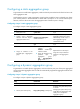
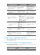
Task Command
Display the local system ID.
display lacp system-id
Display the global or group-specific
link-aggregation load sharing criteria.
display link-aggregation load-sharing mode [ interface
[ route-aggregation interface-number ] ]
Display detailed link aggregation information
for link aggregation member ports.
display link-aggregation member-port [ interface-list ]
Display summary information about all
aggregation groups.
display link-aggregation summary
Display detailed information about the specified
aggregation groups.
display link-aggregation verbose [ route-aggregation
[ interface-number ] ]
Clear LACP statistics for the specified link
aggregation member ports.
reset lacp statistics [ interface interface-list ]
Clear statistics for the specified aggregate
interfaces.
reset counters interface [ route-aggregation
[ interface-number ] ]
Ethernet link aggregation configuration examples
Layer 3 static aggregation configuration example
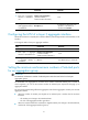
Network requirements
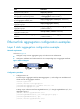
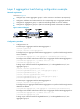
As shown in Figure 4:
• Configure a Layer 3 static aggregation group on both Device A and Device B.
• Configure IP addresses and subnet masks for the corresponding Layer 3 aggregate interfaces.
Figure 4 Network diagram
Configuration procedure
1. Configure Device A:
# Create Layer 3 aggregate interface Route-Aggregation 1, and configure an IP address and
subnet mask for the aggregate interface.
<DeviceA> system-view
[DeviceA] interface route-aggregation 1
[DeviceA-Route-Aggregation1] ip address 192.168.1.1 24
[DeviceA-Route-Aggregation1] quit
# Assign Layer 3 Ethernet interfaces GigabitEthernet 2/1/1 through GigabitEthernet 2/1/3 to
aggregation group 1.
[DeviceA] interface gigabitethernet 2/1/1
[DeviceA-GigabitEthernet2/1/1] port link-aggregation group 1
[DeviceA-GigabitEthernet2/1/1] quit
[DeviceA] interface gigabitethernet 2/1/2