
R0106-HP MSR Router Series Layer 2 - LAN Switching Configuration Guide(V7)

36
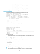
Table 3 Selecting the optimum configuration BPDU
Ste
p
Actions
1
Upon receiving a configuration BPDU on a port, the device compares the priority of the
received configuration BPDU with that of the configuration BPDU generated by the port:
• If the former priority is lower, the device discards the received configuration BPDU and
keeps the configuration BPDU the port generated.
• If the former priority is higher, the device replaces the content of the configuration BPDU
generated by the port with the content of the received configuration BPDU.
2
The device compares the configuration BPDUs of all the ports and chooses the optimum
configuration BPDU.
The following are the principles of configuration BPDU comparison:
a. The configuration BPDU with the lowest root bridge ID has the highest priority.
b. If configuration BPDUs have the same root bridge ID, their root path costs are compared. For
example, the root path cost in a configuration BPDU plus the path cost of a receiving port is S.
The configuration BPDU with the smallest S value has the highest priority.
c. If all configuration BPDUs have the same root bridge ID and S value, the following attributes
are compared in sequence:
− Designated bridge IDs.
− Designated port IDs.
− IDs of the receiving ports.
The configuration BPDU that contains a smaller designated bridge ID, designated port ID, or
receiving port ID is selected.
A tree-shape topology forms when the root bridge, root ports, and designated ports are selected.
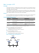
Example of STP calculation
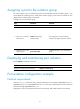
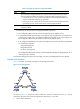
Figure 10 provides an example showing how the STP algorithm works.
Figure 10 The STP algorithm
As shown in Figure 10, the priority values of Device A, Device B, and Device C are 0, 1, and 2,
respectively. The path costs of links among the three devices are 5, 10, and 4.
1. Device state initialization.