
R0106-HP MSR Router Series Layer 2 - LAN Switching Configuration Guide(V7)

78
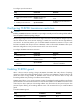
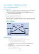
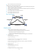
• Device C and Device D work at the access layer.
Configure PVST to meet the following requirements:
• Packets of VLAN 10, VLAN 20, VLAN 30, and VLAN 40 are forwarded along the spanning trees
of VLAN 10, VLAN 20, VLAN 30, and VLAN 40.
• VLAN 10, VLAN 20, and VLAN 30 are terminated on the distribution layer devices, and VLAN 40
is terminated on the access layer devices.
• The root bridge of VLAN 10 and VLAN 20 as Device A.
• The root bridge of VLAN 30 as Device B.
• The root bridge of VLAN 40 as Device C.
Figure 21 Network diagram
Configuration procedure
1. Configure VLANs and VLAN member ports: (Details not shown.)
{ Create VLAN 10, VLAN 20, and VLAN 30 on both Device A and Device B.
{ Create VLAN 10, VLAN 20, and VLAN 40 on Device C.
{ Create VLAN 20, VLAN 30, and VLAN 40 on Device D.
{ Configure the ports on these devices as trunk ports and assign them to related VLANs.
2. Configure Device A:
# Set the spanning tree mode to PVST.
<DeviceA> system-view
[DeviceA] stp mode pvst
# Configure the device as the root bridge of VLAN 10 and VLAN 20.
[DeviceA] stp vlan 10 20 root primary
# Enable the spanning tree feature globally and in VLAN 10, VLAN 20, and VLAN 30.
[DeviceA] stp global enable
[DeviceA] stp vlan 10 20 30 enable
3. Configure Device B:
# Set the spanning tree mode to PVST.
<DeviceB> system-view
[DeviceB] stp mode pvst
# Configure the device as the root bridge of VLAN 30.
G
E
2
/
1
/
1
G
E
2
/
1
/
1
GE
2
/
1
/
1
G
E
2
/
1
/
1