HP MSR Router Series Layer 2 - WAN Access Configuration Guide(V7) Part number: 5998-5676 Software version: CMW710-R0106 Document version: 6PW100-20140607
Legal and notice information © Copyright 2014 Hewlett-Packard Development Company, L.P. No part of this documentation may be reproduced or transmitted in any form or by any means without prior written consent of Hewlett-Packard Development Company, L.P. The information contained herein is subject to change without notice.
Contents Configuring PPP and MP ············································································································································· 1 PPP overview······································································································································································ 1 PPP link establishment process ····························································································································
PPPoE client in on-demand mode configuration example ················································································· 51 PPPoE client in diagnostic mode configuration example ·················································································· 52 Configuration example for connecting a LAN to the Internet through an ADSL modem ······························· 53 Configuring L2TP ····································································································
Configuration restrictions and guidelines ··········································································································· 88 Configuration procedure ······································································································································ 88 Displaying and maintaining HDLC link bundling ······································································································· 89 HDLC link bundling configuration example ···
Configuring applications carried by ATM ················································································································ 118 Configuring a VE interface ································································································································· 119 Configuring IPoA ················································································································································· 120 Configuring IPoEoA·········
3G modem management configuration example ····································································································· 150 Network requirements ········································································································································· 150 Configuration procedure ···································································································································· 150 4G modem management configuration exampl
Dynamic route backup for traditional DDR configuration example ······························································· 202 Dynamic route backup for bundle DDR configuration example ····································································· 204 Configuration example for dynamic route backup for multiple networks ····················································· 207 Troubleshooting ··········································································································
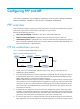
Configuring PPP and MP In this chapter, "MSR2000" refers to MSR2003. "MSR3000" collectively refers to MSR3012, MSR3024, MSR3044, MSR3064. "MSR4000" collectively refers to MSR4060 and MSR4080. PPP overview Point-to-Point Protocol (PPP) is a point-to-point link layer protocol. It provides user authentication, supports synchronous/asynchronous communication, and allows for easy extension. PPP includes the following protocols: • Link control protocol (LCP)—Establishes, tears down, and monitors data links.
becomes ready to carry negotiated network-layer protocol packets. If the NCP negotiation fails, NCP reports a Down event and enters the Link Termination phase. If the interface is configured with an IP address, the IPCP negotiation is performed. IPCP configuration options include IP addresses and DNS server IP addresses. After the IPCP negotiation succeeds, the link can carry IP packets. 5.
packet and distributes the fragments across multiple PPP links to the peer. After the peer receives these fragments, it reassembles them into one packet and passes the packet to the network layer. In addition to increasing bandwidth, MP also provides link-layer load sharing, which can implement backup. MP fragmentation can reduce transmission delay, especially on low-speed links.
Configuring PAP authentication To configure the authenticator: Step Command Remarks 1. Enter system view. system-view N/A 2. Enter interface view. interface interface-type interface-number N/A 3. Configure the authenticator to authenticate the peer by using PAP. ppp authentication-mode pap [ [ call-in ] domain isp-name ] By default, PPP authentication is disabled. For local AAA authentication, the username and password of the peer must be configured on the authenticator. 4.
Step Command Remarks The default setting is null. 4. Configure a username for the CHAP authenticator. ppp chap user username For local AAA authentication, the username and password of the peer must be configured on the authenticator. 5. Configure local or remote AAA authentication. For remote AAA authentication, the username and password of the peer must be configured on the remote AAA server. For more information about AAA authentication, see Security Configuration Guide.
Step Command Remarks 2. Enter interface view. interface interface-type interface-number N/A 3. Configure the authenticator to authenticate the peer by using CHAP. ppp authentication-mode chap [ [ call-in ] domain isp-name ] By default, PPP authentication is disabled. For local AAA authentication, the username and password of the peer must be configured on the authenticator. 4. Configure local or remote AAA authentication.
Step Command Remarks 3. Configure the authenticator to authenticate the peer by using MS-CHAP or MS-CHAP-V2. ppp authentication-mode { ms-chap | ms-chap-v2 } [ [ call-in ] domain isp-name ] By default, PPP authentication is disabled. 4. Configure a username for the MS-CHAP or MS-CHAP-V2 authenticator. ppp chap user username The username for the authenticator must be the same on the local and peer devices.
To configure the polling interval: Step Command Remarks 1. Enter system view. system-view N/A 2. Enter interface view. interface interface-type interface-number N/A 3. Configure the polling interval. timer-hold period The default setting is 10 seconds.
1. If the AAA server assigns an IP address to the client or has a specified address pool, the server assigns that IP address or an IP address from the specified address pool to the client. The IP address or address pool is configured on the AAA server instead of the PPP server. 2. If an address pool is associated with the ISP domain used during client authentication, the server assigns an IP address from the associated address pool to the client. 3.
Step Command Remarks 2. Configure an address pool. ip pool pool-name start-ip-address [ end-ip-address ] [ group group-name ] By default, no address pool is configured. 3. Enter interface view. interface interface-type interface-number N/A 4. Configure the interface to assign an IP address from the configured address pool to the peer. remote address pool pool-name By default, an interface does not assign an IP address to the peer. 5. Configure an IP address for the interface.
Step Command Remarks 1. Enter system view. system-view N/A 2. Enter interface view. interface interface-type interface-number N/A 3. Enable the device to request the peer for a DNS server IP address. ppp ipcp dns request By default, a client does not request its peer for a DNS server IP address. ppp ipcp dns admit-any By default, a device does not accept the DNS server IP addresses assigned by the peer if it does not request the peer for the DNS server IP addresses. 4.
Step Command Remarks 1. Enter system view. system-view N/A 2. Enter interface view. interface interface-type interface-number N/A 3. Configure the ACCM value. ppp accm hex-number By default, the ACCM value is 0x000A0000. The ACCM negotiation option applies only to asynchronous links. Configuring ACFC negotiation PPP can compress the address and control fields of PPP packets to increase the payload size.
PFC negotiation notifies the peer that the local end can receive packets with a single-byte protocol field. PFC negotiation is implemented at the LCP negotiation stage. After PFC negotiation is completed, the device compresses the protocol field of sent non-LCP packets. If the first eight bits of the protocol field are all zeros, the device does not add those bits into the packet. To ensure successful LCP negotiation, PPP does not apply the compression to LCP packets.
Step Command Remarks 2. Enter interface view. interface interface-type interface-number N/A 3. Enable PPP accounting. ppp account-statistics enable [ acl { acl-number | name acl-name } ] By default, PPP accounting is disabled. Support for the acl keyword depends on the device model. Enabling IP header compression IP header compression (IPHC) compresses packet headers to speed up packet transmission. IPHC is often used for voice communications over low-speed links.
Configuring MP MP supports binding interfaces on the same LPU rather than on different LPUs. You can configure MP by using virtual template (VT) or MP-group interfaces: • VT interfaces—VT interfaces are used to configure VA interfaces. After binding multiple PPP links into an MP link, you must create a VA interface for the MP link to exchange data with the peers. VT interfaces support authentication.
When you configure MP by using a VT interface, follow these guidelines: • The ppp mp command and the ppp mp virtual-template command are mutually exclusive on an interface. • You must use the same method to configure the interfaces to be bundled . • To use one-way authentication, associate physical interfaces to a VT interface on one end and associate a username to the VT interface on the other end. • Configure a VT interface to provide only one service, such as MP, L2TP, or PPPoE.
Step Command Remarks • (Method 1) Bind a physical interface to the VT interface: a. Enter interface view: interface interface-type interface-number b. Bind the interface to the specified VT interface, and enable MP for the interface: ppp mp virtual-template number c. 10. Associate a physical interface or a username to the VT interface. By default, a physical interface is enabled with PPP and not bound to any VT interfaces. (Optional.) Configure PPP authentication (see "Configuring PPP authentication.
Step Command Remarks The default setting is 0, which means MP dialup depends on traffic detection. 5. (Optional.) Set the minimum number of links in an MP bundle. ppp mp min-bind min-bind-num 6. Set the minimum size of MP fragments. ppp mp min-fragment size The default setting is128 bytes. 7. Configure the MP sort buffer size factor. ppp mp sort-buffer-size size The default setting is 1. 8. (Optional.) Configure the timer for MP to wait for the expected fragment.
Step Command Remarks By default, MP fragmentation is enabled. 7. (Optional.) Disable MP fragmentation. ppp mp fragment disable After you configure this command on an interface, the settings configured with the ppp mp lfi enable and ppp mp min-fragment commands do not take effect on the interface. Optional. 8. (Optional.) Set the interface description. description text The default setting is interface name Interface, for example, MP-group3 Interface. 9. Set the polling interval.
Step Command Remarks 1. Enter system view system-view N/A 2. Enter interface view. interface interface-type interface-number N/A 3. Trigger MP short sequence number header negotiation, specifying that the interface receive fragments with short sequence numbers after the negotiation succeeds. ppp mp short-sequence By default, long sequence number header format negotiation is performed.
Figure 2 LFI WFQ Fragmentation Large packet Output queue WFQ Voice packet Traffic classifying To configure LFI: Step Command Remarks 1. Enter system view. system-view N/A 2. Enter VT interface, MP-group interface, or dialer interface view. interface { dialer | mp-group | virtual-template } mp-number N/A By default, LFI is disabled. 3. Enable LFI. 4. Set the maximum LFI fragment transmission delay and the maximum LFI fragment size (in bytes).
Task Command Clear the statistics for VA interfaces. reset counters interface [ virtual-access [ interface-number ] ] Clear the statistics for MP-group interfaces. reset counters interface [ mp-group [ interface-number ] ] PPP configuration examples One-way PAP authentication configuration example Network requirements As shown in Figure 3, configure Router A to authenticate Router B by using PAP, but Router B not to authenticate Router A. Figure 3 Network diagram Configuration procedure 1.
[RouterB] interface serial 2/1/0 [RouterB-Serial2/1/0] link-protocol ppp # Configure the PAP username and password sent from Router B to Router A when Router B is authenticated by Router A using PAP. [RouterB-Serial2/1/0] ppp pap local-user userb password simple passb # Assign an IP address to Serial 2/1/0 of Router B. [RouterB-Serial2/1/0] ip address 200.1.1.2 16 3. Verify the configuration: Use the display interface serial command to display information about Serial 2/1/0 of Router B.
Configuration procedure 1. Configure Router A: # Create a user account for Router B. system-view [RouterA] local-user userb class network # Set a password for the user account. [RouterA-luser-network-userb] password simple passb # Set the service type of the user account to PPP. [RouterA-luser-network-userb] service-type ppp [RouterA-luser-network-userb] quit # Enable PPP encapsulation on Serial 2/1/0 (optional, as an interface uses PPP encapsulation by default).
[RouterB-Serial2/1/0] quit # Configure local authentication for the PPP users in the default ISP domain system. [RouterB] domain system [RouterB-isp-system] authentication ppp local 3. Verify the configuration: Use the display interface serial command to display information about Serial 2/1/0 of Router B. The physical layer status and link layer status of the interface are both up. The states of LCP and IPCP are both Opened, indicating that PPP negotiation is successful.
[RouterA] local-user userb class network # Set a password for the user account. [RouterA-luser-network-userb] password simple hello # Set the service type of the user account to PPP. [RouterA-luser-network-userb] service-type ppp [RouterA-luser-network-userb] quit # Enable PPP encapsulation on Serial 2/1/0 (optional, as an interface uses PPP encapsulation by default).
# Set the service type of the user account to PPP. [RouterA-luser-network-userb] service-type ppp [RouterA-luser-network-userb] quit # Set the authentication mode to CHAP. [RouterA] interface serial 2/1/0 [RouterA-Serial2/1/0] ppp authentication-mode chap domain system # Assign an IP address to Serial 2/1/0. [RouterA-Serial2/1/0] ip address 200.1.1.1 16 [RouterA-Serial2/1/0] quit # Configure local authentication for the PPP users in the default ISP domain system.
round-trip min/avg/max/std-dev = 1.738/2.402/3.197/0.576 ms IP address negotiation configuration examples Specifying an IP address for the client on the server interface Network requirements As shown in Figure 6, configure Router A to allocate an IP address to Serial 2/1/0 of Router B through PPP negotiation. The IP address is specified on Serial 2/1/0 of Router A. Figure 6 Network diagram Configuration procedure 1.
--- Ping statistics for 200.1.1.1 --5 packet(s) transmitted, 5 packet(s) received, 0.0% packet loss round-trip min/avg/max/std-dev = 1.738/2.402/3.197/0.576 ms The output shows Serial 2/0 of Router A can be pinged. Specifying an address pool on the server interface Network requirements As shown in Figure 7, configure Router A to allocate an IP address from the address pool on Serial 2/1/0 of Router A to Serial 2/1/0 of Router B through PPP negotiation. Figure 7 Network diagram Configuration procedure 1.
56 bytes from 200.1.1.1: icmp_seq=0 ttl=128 time=3.197 ms 56 bytes from 200.1.1.1: icmp_seq=1 ttl=128 time=2.594 ms 56 bytes from 200.1.1.1: icmp_seq=2 ttl=128 time=2.739 ms 56 bytes from 200.1.1.1: icmp_seq=3 ttl=128 time=1.738 ms 56 bytes from 200.1.1.1: icmp_seq=4 ttl=128 time=1.744 ms --- Ping statistics for 200.1.1.1 --5 packet(s) transmitted, 5 packet(s) received, 0.0% packet loss round-trip min/avg/max/std-dev = 1.738/2.402/3.197/0.576 ms The output shows that the ping operation is successful.
[RouterA-isp-bbb] authorization-attribute ip-pool aaa [RouterA-isp-bbb] quit # Configure Serial 2/1/0 to authenticate the peer interface in the ISP domain bbb by using PAP. [RouterA] interface serial 2/1/0 [RouterA-Serial2/1/0] ppp authentication-mode pap domain bbb # Configure an IP address for Serial 2/1/0. [RouterA-Serial2/1/0] ip address 200.1.1.1 16 2. Configure Router B: # Configure the username and password for PAP authentication by Router A.
200.1.1.10 S2/1/0 The output shows that one IP address of the address pool aaa has been assigned. MP binding mode configuration examples Network requirements As shown in Figure 9, to enable MP for Serial 2/1/0 and Serial 2/1/1, use one of the following methods: • Bind the physical interfaces to a VT interface. • Associate remote usernames with a VT interface. • Configure an MP-group interface.
[RouterB-Serial2/1/1] quit # Configure Serial 2/1/0. [RouterB] interface serial 2/1/0 [RouterB-Serial2/1/0] link-protocol ppp [RouterB-Serial2/1/0] ppp mp virtual-template 1 [RouterB-Serial2/1/0] quit 3. Verify the configuration: # Display MP information on Router A.
56 bytes from 8.1.1.1: icmp_seq=3 ttl=255 time=0.000 ms 56 bytes from 8.1.1.1: icmp_seq=4 ttl=255 time=1.000 ms --- Ping statistics for 8.1.1.1 --5 packet(s) transmitted, 5 packet(s) received, 0.0% packet loss round-trip min/avg/max/std-dev = 0.000/1.000/4.000/1.549 ms (Method 2) Associate remote usernames with a VT interface. 5. Configure Router A: # Configure the usernames, and passwords of remote users.
[RouterB-luser-network-userc] quit [RouterB] local-user userd class network [RouterB-luser-network-userd] password simple ddd [RouterB-luser-network-userd] service-type ppp [RouterB-luser-network-userd] quit # Bind a VT interface to users. [RouterB] ppp mp user userc bind virtual-template 1 [RouterB] ppp mp user userd bind virtual-template 1 # Create the VT interface and configure its IP address. [RouterB] interface virtual-template 1 [RouterB-Virtual-Template1] ip address 8.1.1.
Serial2/1/0 Up-Time:2013/01/10 08:06:26:634 # Display the MP information on Router B.
Maximum Transmit Unit: 1500 Hold timer: 10 seconds Internet Address is 8.1.1.
9. Configure Router B: # Create an MP-group interface, and configure an IP address for it. [RouterB] interface mp-group 1 [RouterB-Mp-group1] ip address 1.1.1.2 24 [RouterB-Mp-group1] quit # Configure interface Serial 2/1/1. [RouterB] interface serial 2/1/1 [RouterB-Serial2/1/1] link-protocol ppp [RouterB-Serial2/1/1] ppp mp mp-group 1 [RouterB-Serial2/1/1] shutdown [RouterB-Serial2/1/1] undo shutdown [RouterB-Serial2/1/1] quit # Configure interface Serial 2/1/0.
Output queue - Protocol queuing: Size/Length/Discards 0/500/0 Output queue - FIFO queuing: Size/Length/Discards 0/75/0 Last clearing of counters: Never Last 300 seconds input rate: 0 bytes/sec, 0 bits/sec, 0 packets/sec Last 300 seconds output rate: 0 bytes/sec, 0 bits/sec, 0 packets/sec Input: 2 packets, 80 bytes, 0 drops Output: 2 packets, 24 bytes, 0 drops # Ping Router B from Router A. [RouterA] ping 1.1.1.2 Ping 1.1.1.2 (1.1.1.2): 56 data bytes, press CTRL_C to break 56 bytes from 1.1.1.
Configuring PPPoE Overview Point-to-Point Protocol over Ethernet (PPPoE) extends PPP by transporting PPP frames encapsulated in Ethernet over point-to-point links. PPPoE specifies the methods for establishing PPPoE sessions and encapsulating PPP frames over Ethernet. PPPoE requires a point-to-point relationship between peers instead of a point-to-multipoint relationship as in multi-access environments such as Ethernet.
• As shown in Figure 11, a PPPoE session is established between each host (PPPoE client) and the carrier router (PPPoE server). The service provider assigns an account to each host for billing and control. The host must be installed with PPPoE client software. Figure 11 Network structure 2 PPPoE client Host A PPPoE server Internet PPPoE client Router Host B Configuring the PPPoE server Configuring a PPPoE session Step Command Remarks 1. Enter system view. system-view N/A 2.
Step Command Remarks 10. Configure the PPPoE server to perform authentication and accounting for PPP users. See Security Configuration Guide. N/A Setting the maximum number of PPPoE sessions PPPoE can establish a session when none of the following maximum numbers are reached: • The maximum number of PPPoE sessions for a user on an interface. • The maximum number of PPPoE sessions for a VLAN on an interface. • The maximum number of PPPoE sessions on an interface.
threshold, the device discards the excessive requests, and outputs log messages. If the blocking time is set to 0, the device does not block any requests, and it only outputs log messages. The device uses a monitoring table and a blocking table to control PPP access rates: • Monitoring table—Stores a maximum of 8000 monitoring entries. Each entry records the number of PPPoE sessions created by a user within the monitoring time.
Step Command Remarks 2. Enter Layer 3 Ethernet interface, Layer 3 virtual Ethernet interface, or Layer 3 aggregate interface view. interface interface-type interface-number The PPPoE server is enabled on the interface. 3. Configure the access line ID content. pppoe-server access-line-id content { all [ separator ] | circuit-id | remote-id } By default, the access line ID includes only the circuit-id. 4. Configure the PPPoE server to trust the access line ID in received packets.
Step Command Remarks 1. Enter system view. system-view N/A 2. Create a VA pool (MSR2000/MSR3000). pppoe-server virtual-template template-number va-pool va-volume By default, no VA pool exists. 3. Create a VA pool (MSR4000). pppoe-server virtual-template template-number [ slot slot-number ] va-pool va-volume By default, no VA pool exists. Clearing PPPoE sessions To clear PPPoE sessions on the PPPoE server: Step Command Remarks 1. Enter user view. user-view N/A 2. Clear PPPoE sessions.
For more information about configuring dialer interfaces, bundle DDR, and dialer bundles, see "Configuring DDR." Configuring a dialer interface for a PPPoE client Step Command Remarks 1. Enter system view. system-view N/A 2. Create a dialer access group and configure a dial access control rule. dialer-group dialer-group rule { protocol-name { deny | permit } | acl { acl-number | name acl-number } By default, no dialer group exists. 3. Create a dialer interface and enter its view.
Step Command Remarks By default, the MTU on a dialer interface is 1500 bytes. 10. Set the MTU for the dialer interface The dialer interface fragments a packet that exceeds the configured MTU, and adds a 2-byte PPP header and a 6-byte PPPoE header to each fragment. You should modify the MTU of a dialer interface to make sure the total length of any fragment packet is less than the MTU of the physical interface. mtu size Configuring a PPPoE session Step Command Remarks 1. Enter system view.
Displaying and maintaining PPPoE Displaying and maintaining PPPoE server Execute display commands in any view. Task Command Display summary information for PPPoE sessions (MSR2000/MSR3000). display pppoe-server session summary [ interface interface-type interface-number ] Display summary information for PPPoE sessions (MSR4000). display pppoe-server session summary [ slot slot-number | interface interface-type interface-number ] Display packet statistics for PPPoE sessions (MSR2000/MSR3000).
Figure 12 Network diagram Host A Router GE1/0/1 S2/1/0 Internet Host B Configuration procedure 1. Create a PPPoE user. system-view [Router] local-user user1 class network [Router-luser-network-user1] password simple pass1 [Router-luser-network-user1] service-type ppp [Router-luser-network-user1] quit 2. Configure interface VT 1 to use CHAP for authentication and use an address pool for IP address assignment.
Figure 13 Network diagram Configuration procedure 1. Configure Router A as the PPPoE server: # Configure an IP address for interface VT 1 and specify an IP address for the peer. system-view [RouterA] interface virtual-template 1 [RouterA-Virtual-Template1] ip address 1.1.1.1 255.0.0.0 [RouterA-Virtual-Template1] remote address 1.1.1.2 [RouterA-Virtual-Template1] quit # Enable the PPPoE server on GigabitEthernet 1/0/1, and bind the interface to VT 1.
[RouterB-Dialer1] display pppoe-client session summary Bundle ID Interface VA RemoteMAC 1 GE1/0/1 VA0 00e0-1400-4300 00e0-1500-4100 SESSION 1 LocalMAC State PPPoE client in on-demand mode configuration example Network requirements As shown in Figure 14, Router A serves as a PPPoE server. Configure Router B as a PPPoE client operating in on-demand mode, and set the link idle-timeout timer to 150 seconds. Figure 14 Network diagram Configuration procedure 1.
[RouterB] ip route-static 1.1.1.1 255.0.0.0 dialer 1 # Set the link-idle timeout timer to 150 seconds. [RouterB] interface dialer 1 [RouterB-Dialer1] dialer timer idle 150 [RouterB-Dialer1] quit 3. Verify the configuration by displaying summary information about the PPPoE session established between Router B and Router A (PPPoE server).
[RouterB-Dialer1] ip address ppp-negotiate # Configure a PPPoE session that corresponds to dialer bundle 1 (dialer bundle 1 corresponds to Dialer 1). [RouterB] interface gigabitethernet 1/0/1 [RouterB-GigabitEthernet1/0/1] pppoe-client dial-bundle-number 1 [RouterB-GigabitEthernet1/0/1] quit # Configure the PPPoE session to operate in diagnostic mode, and set the diagnostic interval to 200 seconds.
Figure 16 Network diagram Configuration procedure 1. Configure Router A as a PPPoE client: # Create dialer access group 1 and configure a dial access control rule for it. system-view [RouterA] dialer-group 1 rule ip permit # Enable bundle DDR on interface Dialer 1. [RouterA] interface dialer 1 [RouterA-Dialer1] dialer bundle enable # Associate Dialer 1 with dialer access group 1. [RouterA-Dialer1] dialer-group 1 # Configure Dialer 1 to obtain an IP address through PPP negotiation.
# Configure a default route. [RouterA] ip route-static 0.0.0.0 0 dialer 1 If the hosts in the LAN use private addresses, configure NAT on Router A. For more information about NAT, see Layer 3—IP Services Configuration Guide. 2. Configure Router B as the PPPoE server: # Configure virtual template 1 to use PAP for authentication and use an address pool to assign IP addresses.
4. Verify the configuration by displaying summary information for the PPPoE session between Router A and Router B. [RouterA] display pppoe-client session summary Bundle ID Interface VA RemoteMAC 1 GE1/0/1 VA0 0001-0000-0001 00e0-1500-4100 SESSION 1 LocalMAC State Host A, HostB, and Host C can thus access the Internet. For example, they can browse a web page through IE.
Configuring L2TP In this chapter, "MSR4000" collectively refers to MSR4060 and MSR4080. Overview The Layer 2 Tunneling Protocol (L2TP) is the most widely used Virtual Private Dialup Network (VPDN) tunneling protocol. L2TP sets up point-to-point tunnels across a public network (for example, the Internet) and transmits encapsulated PPP frames (L2TP packets) over the tunnels.
L2TP message types and encapsulation structure L2TP uses the following types of messages: • Control messages—Used to establish, maintain, and delete L2TP tunnels and sessions. Control messages are transmitted over a reliable control channel, which supports flow control and congestion control. • Data messages—Used to encapsulate PPP frames, as shown in Figure 18. Data messages are transmitted over an unreliable data channel and are not retransmitted when packet loss occurs.
Figure 20 NAS-initiated tunneling mode A NAS-initiated tunnel has the following characteristics: • The remote system only needs to support PPP, and does not need to support L2TP. • Authentication and accounting of the remote system can be implemented on the LAC or the LNS.
4. The LAC sends the authentication information (username and password) to its RADIUS server (RADIUS server A) for authentication. 5. RADIUS server A authenticates the user and returns the result. 6. If the user passes the authentication and the user is determined to be an L2TP user according to the username or the ISP domain to which the user belongs, the LAC initiates an L2TP tunneling request to the LNS (Device B). 7.
As shown in Figure 23, the workflow for establishing a client-initiated tunnel is similar to that for establishing a NAS-initiated tunnel. (Details not shown.
Figure 25 Establishment process for LAC-auto-initiated tunnels L2TP features • Flexible identity authentication mechanism and high security—L2TP by itself does not provide security for connections. However, it has all the security features of PPP and allows for PPP authentication (CHAP or PAP). L2TP can also cooperate with IPsec to guarantee data security, strengthening the guard against attacks for tunneled data.
Table 1 Tunnel attributes that can be issued by the RADIUS server Attribute number Attribute name Description 64 Tunnel-Type Tunnel type, which can only be L2TP. 65 Tunnel-Medium-Type Transmission medium type for the tunnel, which can only be IPv4. 67 Tunnel-Server-Endpoint IP address of the LNS. 69 Tunnel-Password Key used to authenticate a peer of the tunnel. Group ID for the tunnel.
Tasks at a glance Remarks Configuring an LAC • (Required.) Configuring an LAC to initiate tunneling requests for a specified user • • • • (Required.) Specifying LNS IP addresses (Optional.) Configuring transferring AVP data in hidden mode (Required.) Configuring AAA authentication on an LAC (Required.) Configuring an LAC to automatically establish an L2TP tunnel The first and fourth tasks are required for NAS-initiated mode and unnecessary for LAC-auto-initiated mode.
• Configuring the local tunnel name—The local tunnel name identifies the tunnel at the local end during tunnel negotiation between an LAC and an LNS. To configure basic L2TP capabilities: Step Command Remarks 1. Enter system view. system-view N/A 2. Enable L2TP. l2tp enable By default, L2TP is disabled. 3. Create an L2TP group, specify its mode, and enter its view. l2tp-group group-number mode { lac | lns } By default, no L2TP group exists.
Specifying LNS IP addresses You can specify up to five LNS IP addresses. The LAC initiates an L2TP tunneling request to its specified LNSs consecutively in their configuration order until it receives an acknowledgement from an LNS. That LNS then becomes the tunnel peer. To specify LNS IP addresses: Step Command Remarks 1. Enter system view. system-view N/A 2. Enter L2TP group view in LAC mode. l2tp-group group-number [ mode lac ] N/A 3. Specify LNS IP addresses.
To enable AAA authentication on an LAC, you also need to configure the authentication type of PPP users as PAP or CHAP on the user access interfaces. For information about configuring PAP or CHAP, see "Configuring PPP and MP." Configuring an LAC to automatically establish an L2TP tunnel To configure an LAC to automatically establish an L2TP tunnel, perform the following tasks: • Create a virtual PPP interface and configure an IP address for the interface.
Step Command Remarks 10. (Optional.) Restore the default settings for the interface. default N/A 11. (Optional.) interface. undo shutdown By default, an interface is up. Bring up the Configuring an LNS An LNS responds to the tunneling requests from an LAC, authenticates users, and assigns IP addresses to users. Creating a VT interface After an L2TP session is established, a virtual access (VA) interface is needed for data exchange with the peer.
Step 3. Configure the LNS to accept tunneling requests from a specified LAC and specify the VT interface to be used for tunnel setup. Command Remarks • If the L2TP group number is 1: Use either command. allow l2tp virtual-template virtual-template-number [ remote remote-name ] • If the L2TP group number is not 1: allow l2tp virtual-template virtual-template-number remote remote-name By default, an LNS denies tunneling requests from any LAC.
Step Command Remarks 1. Enter system view. system-view N/A 2. Enter L2TP group view in LNS mode. l2tp-group group-number [ mode lns ] N/A 3. Configure mandatory CHAP authentication. mandatory-chap By default, CHAP authentication is not performed on an LNS. This command is effective only on NAS-initiated L2TP tunnels. Configuring LCP renegotiation To establish a NAS-initiated L2TP tunnel, a user first negotiates with the LAC at the start of a PPP session.
Configuring optional L2TP parameters The optional L2TP parameter configuration tasks apply to both LACs and LNSs. Configuring L2TP tunnel authentication You can enable tunnel authentication to allow the LAC and LNS to authenticate each other. Either the LAC or the LNS can initiate a tunnel authentication request. To implement tunnel authentication, enable tunnel authentication on both the LAC and LNS, and configure the same non-null key on them. To ensure tunnel security, enable tunnel authentication.
To enable session flow control: Step Command Remarks 1. Enter system view. system-view N/A 2. Enter L2TP group view. l2tp-group group-number [ mode { lac | lns } ] N/A 3. Enable the session flow control function. tunnel flow-control By default, this function is disabled. Configuring the DSCP value of L2TP packets The Differentiated Services Code Point (DSCP) field is the first 6 bits of the IP ToS byte. This field marks the priority of IP packets for forwarding.
Displaying and maintaining L2TP Execute display commands in any view and reset commands in user view. Task Command Display L2TP tunnel information. display l2tp tunnel [ statistics ] Display L2TP session information. display l2tp session [ statistics ] Display information about virtual PPP interfaces. display interface [ virtual-ppp [ interface-number ] ] [ brief [ description | down ] ] Disconnect a specified L2TP tunnel.
[LAC-Async2/1/0] quit # Enable L2TP. [LAC] l2tp enable # Create L2TP group 1 in LAC mode. [LAC] l2tp-group 1 mode lac # Configure the local tunnel name as LAC. [LAC-l2tp1] tunnel name LAC # Specify PPP user vpdnuser as the condition for the LAC to initiate tunneling requests. [LAC-l2tp1] user fullusername vpdnuser # Specify the LNS IP address as 1.1.2.2. [LAC-l2tp1] lns-ip 1.1.2.2 # Enable tunnel authentication, and specify the tunnel authentication key as aabbcc.
# Enable tunnel authentication, and specify the tunnel authentication key as aabbcc. [LNS-l2tp1] tunnel authentication [LNS-l2tp1] tunnel password simple aabbcc [LNS-l2tp1] quit 3. On the remote system, enter vpdnuser as the username and Hello as the password in the dial-up network window to dial a connection. Verifying the configuration After the dial-up connection is established, the remote system can obtain an IP address (for example, 192.168.0.2) and can ping the private IP address of the LNS (192.
# Create a local user named vpdnuser, set the password, and enable the PPP service. [LNS] local-user vpdnuser class network [LNS-luser-network-vpdnuser] password simple Hello [LNS-luser-network-vpdnuser] service-type ppp [LNS-luser-network-vpdnuser] quit # Configure local authentication for PPP users in ISP domain system. [LNS] domain system [LNS-isp-system] authentication ppp local [LNS-isp-system] quit # Enable L2TP. [LNS] l2tp enable # Create interface Virtual-Template 1.
Verifying the configuration # On the remote host, initiate the L2TP connection. After the connection is established, the remote host can obtain the IP address 192.168.0.2 and ping the private IP address of the LNS (192.168.0.1). # On the LNS, use the display l2tp session command to check the established L2TP session. [LNS-l2tp1] display l2tp session LocalSID RemoteSID LocalTID State 89 36245 10878 Established # On the LNS, use the display l2tp tunnel command to check the established L2TP tunnel.
[LNS] domain system [LNS-isp-system] authentication ppp local [LNS-isp-system] quit # Enable L2TP, and create L2TP group 1 in LNS mode. [LNS] l2tp enable [LNS] l2tp-group 1 mode lns # Configure the local tunnel name as LNS, and specify Virtual-Template 1 for receiving tunneling requests from a specified LAC. [LNS-l2tp1] tunnel name LNS [LNS-l2tp1] allow l2tp virtual-template 1 remote LAC # Enable tunnel authentication, and configure the authentication key as aabbcc.
Verifying the configuration # On the LNS, use the display l2tp session command to display the established L2TP session. [LNS] display l2tp session LocalSID RemoteSID LocalTID State 21409 3395 4501 Established # On the LNS, use the display l2tp tunnel command to display the established L2TP tunnel. [LNS] display l2tp tunnel LocalTID RemoteTID State Sessions RemoteAddress RemotePort RemoteName 4501 1 1701 524 Established 3.3.3.1 LAC # On the LNS, you should be able to ping 10.2.0.
Symptom 2: Data transmission failure Data transmission fails. A connection is established, but data cannot be transmitted. For example, the LAC and LNS cannot ping each other. Analysis and solution Possible reasons for the data transmission failure are as follows: • No route is available. The LAC must have a route to the private network behind the LNS, and vice versa. Otherwise, data transmission fails.
Configuring HDLC This feature is supported only on routers installed with SAE, E1, E1-F, T1, T1-F, POS, CPOS, CE3, or CT3 interface modules. High-level Data Link Control (HDLC) is a bit-oriented link layer protocol. Its most prominent feature is that it can transmit any type of bit stream transparently. • HDLC supports point-to-point link only and does not support point-to-multipoint link. • HDLC supports neither IP address negotiation nor authentication. It uses keepalives to check link status.
Step Command Remarks 1. Enter system view. system-view N/A 2. Enter interface view. interface interface-type interface-number N/A 3. Configure the link status polling interval. timer hold seconds Optional. The default setting is 10 seconds. Displaying and maintaining HDLC Execute display commands in any view and reset commands in user view. Task Command Display the HDLC configuration on an interface.
[RouterA-Pos2/2/0] quit Configuring Router B # Enable HDLC encapsulation on POS 2/2/0. system-view [RouterB] interface pos 2/2/0 [RouterB-Pos2/2/0] link-protocol hdlc # Assign an IP address to POS 2/2/0. [RouterB-Pos2/2/0] ip address 12.1.1.2 24 Verifying the configuration # Ping a router from the other router, for example, ping Router B from Router A. [RouterA] ping 12.1.1.2 Ping 12.1.1.2 (12.1.1.2): 56 data bytes, press CTRL_C to break 56 bytes from 12.1.1.2: icmp_seq=0 ttl=254 time=2.
Configuring HDLC link bundling In this chapter, "MSR2000" refers to MSR2003. "MSR3000" collectively refers to MSR3012, MSR3024, MSR3044, MSR3064. "MSR4000" collectively refers to MSR4060 and MSR4080. This feature is supported only on routers installed with SAE, E1, E1-F, T1, T1-F, POS, CPOS, CE3, or CT3 interface modules. Overview HDLC link bundling bundles multiple interfaces using HDLC encapsulation (also known as HDLC interfaces) together to form one logical link.
• • • Negotiated—The member interface is as follows: { Up at the link layer. { Does not meet the conditions for being a Selected interface in the HDLC link bundle. Ready—The member interface is as follows: { Up at the link layer. { Meets the conditions for being a Selected interface. { Not Selected yet due to the following restrictions: − The maximum number of Selected interfaces. − The minimum number of Selected interfaces required for bringing up the HDLC link bundle.
− Minimum number of Selected interfaces required for bringing up the HDLC link bundle. − Minimum bandwidth required for bringing up the HDLC link bundle. None of the P member interfaces will be Selected and they all stay in the Ready state when any of the following conditions exist: { { P is smaller than Q. The total bandwidths of the P member interfaces is smaller than the minimum bandwidth required for bringing up the HDLC link bundle.
Configuration procedure Step Command Remarks 1. Enter system view. system-view N/A 2. Create an HDLC link bundle interface and enter its view. interface hdlc-bundle bundle-id By default, no HDLC link bundle interface exists. 3. Configure the load balancing mode. bundle load-balance { per-flow | per-packet } By default, per-packet load balancing applies. 4. (Optional.) Specify a card to forward traffic for the HDLC link bundle interface. (MSR4000.
Step Command Remarks By default, an HDLC link bundle interface is up. 12. (Optional.) Bring up the HDLC link bundle interface undo shutdown When an HDLC link bundle interface is brought up, the state of each member interface is re-determined. When an HDLC link bundle interface is shut down, the state of each Selected interface is placed into the Negotiated state.
Step Command Remarks 5. Set the bundling priority for the member interface. bundle member-priority priority The default setting is 32768. Displaying and maintaining HDLC link bundling Execute display commands in any view and reset commands in user view. Task Command Display information about an HDLC link bundle (MSR2000/MSR3000). display bundle hdlc-bundle [ bundle-id ] Display information about an HDLC link bundle (MSR4000).
# Assign POS interfaces POS 2/2/1 to HDLC link bundle 1, and configure the interface to use the master clock mode. [RouterA] interface pos 2/2/1 [RouterA-Pos2/2/1] clock master [RouterA-Pos2/2/1] link-protocol hdlc [RouterA-Pos2/2/1] bundle id 1 [RouterA-Pos2/2/1] quit # Assign POS interfaces POS 2/2/2 to HDLC link bundle 1, and configure the interface to use the master clock mode.
• POS 2/2/1 and POS 2/2/2 are in Selected state and can perform load balancing. • The bandwidth of the HDLC link bundle is 311040 kbps, the total bandwidth of two POS interfaces. • When one POS interface fails, the traffic can be forwarded through the other POS interface. This improves the link reliability. Use Router A as an example.
Configuring ISDN Overview Integrated Services Digital Network (ISDN) is a circuit-switched telephone network system that provides high-quality end-to-end digital connectivity at high rates over copper wire. ISDN transmits all information in the digital form. It enables a single pair of telephone wires to transmit data and voice simultaneously at high rates. This feature enables ISDN to provide more services and higher transmission efficiency than PSTN, where information is transmitted in the analog form.
Item CE1 PRI (30B + D) CT1 PRI (23B + D) Countries/areas • Most Asia countries (including China) • Europe • North America (including USA and Canada) • Hong Kong • Japan ISDN protocol stacks ISDN provides dial-on-demand links. It sets up and maintains a link only when traffic is present. The B-channels and the D-channel use separate protocol stacks, as shown in Table 3. Table 3 ISDN protocol stacks and OSI reference model OSI model ISDN layer D-channel B-channel Network layer Layer 3 Q.
Figure 32 Data ISDN application scenario Figure 33 Voice ISDN application scenario Feature and hardware compatibility ISDN is supported only on the BS, BU, E1, and T1 interface modules. ISDN PRI configuration prerequisites Before you can use a CE1/PRI or CT1/PRI interface to provide ISDN PRI services, you must use the pri-set command to bundle timeslots into channel sets on the interface. For each PRI set, the system creates a serial interface automatically.
Tasks at a glance Remarks (Optional.) Configuring Q.931 call control parameters: • • • • Configuring B-channel selection Configuring calling number verification for incoming calls N/A Configuring called-number verification for incoming calls Configuring ISDN calling number identification Configuring the Q.921 operating parameters: • On a BRI interface: { { { { { { (Required.) Configuring the data link type of a BRI interface (Optional.
NOTE: The device provides full support for DSS1. For any other variants of ISDN, the device only provides the basic call functionality. You cannot perform this task when a call is present on the ISDN interface. To set the service provider switch type on an ISDN interface: Step Command Remarks 1. Enter system view. system-view N/A 2. Enter ISDN BRI or PRI interface view. interface interface-type interface-number N/A The default is DSS1 for both BRI and PRI. 3. Set the ISDN switch type.
Configuring SPID parameters for the NI switch type NI service provider switches use service profile identifications (SPIDs) to identify services (audio, data, or speech) subscribed to by ISDN devices. The service provider assigns one SPID for each B-channel. The device cannot place or receive calls until it sends a valid SPID when it initializes a connection to the service provider switch. Configuring SPID assignment SPIDs can be assigned through static manual configuration or dynamic negotiation.
To configure SPIDs on a BRI interface: Step Command Remarks 1. Enter system view. system-view N/A 2. Enter ISDN BRI interface view. interface bri interface-number N/A 3. Assign a SPID to the B1 channel. isdn spid1 spid [ ldn ] By default, no SPID or LDN is configured for the B1 channel on a BRI interface. 4. Assign a SPID to the B2 channel. isdn spid2 spid [ ldn ] By default, no SPID or LDN is configured for the B2 channel on a BRI interface.
To enable NIT mode: Step Command Remarks 1. Enter system view. system-view N/A 2. Enter ISDN BRI interface view. interface bri interface-number N/A 3. Enable NIT mode. isdn spid nit By default, NIT mode is disabled. The BRI interface performs dynamic SPID negotiation. Configuring Q.931 negotiation parameters Step Command Remarks 1. Enter system view. system-view N/A 2. Enter ISDN BRI or PRI interface view. interface interface-type interface-number N/A 3.
Step 6. (Optional.) Exclude the LLC information element from the outgoing SETUP message. Command Remarks By default, all ISDN protocols except 5ESS and QSIG include the LLC information element in the SETUP message. isdn ignore llc The lower layer compatibility (LLC) element provides low layer compatibility check information for the called party. The called party will reject the call setup request if it detects an incompatibility. By default: 7. (Optional.
Configuring Q.931 call control parameters To ensure successful call setup, make sure the call control parameters match the service provider's settings. Configuring B-channel selection Efficient B-channel selection for calls improves call establishment efficiency and reduces call losses on ISDN lines, especially PRI ISDN lines. By default, ISDN interfaces on the device are operating as the user side, and they do not select B-channels for calls. B-channel selection is done by the service provider switch.
Step Command Remarks 1. Enter system view. system-view N/A 2. Enter ISDN BRI or PRI interface view. interface interface-type interface-number N/A 3. Configure an accepted calling number. isdn caller-number caller-number By default, an ISDN interface accepts calls from any calling numbers. Configuring called-number verification for incoming calls Called-number verification enables an ISDN interface to accept only calls placed to specific called numbers.
Step Command Remarks By default, ISDN interfaces do not send a calling number in outgoing SETUP messages. 3. Specify a calling number. isdn calling calling-number The device will not send the specified calling number if the connected service provider switch does not transmit calling number information. Configuring the Q.921 operating parameters Except for the sliding window configuration, all the Q.921 operating parameter configuration tasks are available only on BRI interfaces.
assignment is not configured, only one B-channel can be brought up. For example, you must configure per-channel TEI assignment when a BRI interface is connected to an ISDN NI compliant DMS-100 switch in the North America. You cannot configure per-channel TEI assignment in the following situations: • The BRI interface's data link type is point-to-point. • A call is present on the interface. To configure per-channel TEI assignment on an ISDN BRI interface: Step Command Remarks 1. Enter system view.
connection is lost, enable persistent Layer 1 activation. This function prevents Q.921 from sending deactivation requests to the physical layer. Persistent Layer 1 activation can only maintain the active state of the physical layer. It does not activate the physical layer if you enable it when the physical layer is inactive. In contrast, Q.921 attempts to set up data link connections if you enable permanent Q.921 link connectivity when no data link connections are present.
Step Command Remarks 1. Enter system view. system-view N/A 2. Enter ISDN BRI interface view. interface bri interface-number N/A 3. Configure the sliding window size. isdn bri-slipwnd-size window-size The default window size is 1. Configuring the sliding window size on an ISDN PRI interface Q.921 sends frames in order of their sequence numbers and requires an acknowledgement of each transmitted frame. To improve transmission efficiency, Q.
ISDN configuration examples ISDN PRI configuration example Network requirements As shown in Figure 34, configure an ISDN PRI line between Router A and Router B for data transmission. Figure 34 Network diagram Router A CE1/PRI 2/3/0 202.38.154.1/16 8810152 ISDN network CE1/PRI 2/3/0 202.38.154.2/16 8810154 Router B Configuration procedure In this example, the ISDN PRI interfaces on Router A and Router B are operating as the user side (the default).
[RouterB-E1 2/3/0] quit # Create dialer access group 1 to allow any IP packets to trigger a call setup. [RouterB] dialer-group 1 rule ip permit # Assign Serial 2/3/0:15 an IP address. [RouterB] interface serial 2/3/0:15 [RouterB-Serial2/3/0:15] ip address 202.38.154.2 255.255.0.0 # Enable C-DDR on the interface, configure the route to Router A, and assign the interface to dialer access group 1. [RouterB-Serial2/3/0:15] dialer circular enable [RouterB-Serial2/3/0:15] dialer route ip 202.38.154.
# Enable C-DDR on the interface, configure the route to Router B, and assign the interface to dialer-group 1. [RouterA-Bri2/4/0] dialer circular enable [RouterA-Bri2/4/0] dialer route ip 202.38.154.2 8810154 [RouterA-Bri2/4/0] dialer-group 1 # Set the switch type to NI on the BRI interface. [RouterA-Bri2/4/0] isdn protocol-type ni # Assign the SPID 54321 to the B1 channel and SPID 65432 to the B2 channel.
• The line is not well connected. Solution To resolve the problem: 1. Execute the display isdn call-info command to verify the interface settings: a. If the command displays nothing, configure an ISDN interface. For more information about configuring BRI, CE1/PRI, and CT1/PRI interfaces, see Interface Configuration Guide. b. Verify the Q.921 state of the PRI or BRI interface: 2. − If the PRI interface's link layer 1 is not in ISDN MULTIPLE_FRAME_ESTABLISHED state, Q.921 negotiation has failed.
Configuring ATM ATM features are applicable to routers installed with ATM-OC3, ADSL2+, G.shdsl, or G.shdsl.Bis interface cards. Overview Asynchronous Transfer Mode (ATM) is a technology based on packet transmission mode while incorporating the high-speed of circuit transmission mode. Due to its flexibility and support for multimedia services, ATM is regarded as a core broadband technology. As defined by the ITU-T, data is encapsulated in cells in ATM.
Figure 37 ATM switching ATM architecture ATM has a three-dimensional architecture. It contains the user plane, control plane, and management plane. Both the user plane and the control plane are divided into the following layers: physical layer, ATM layer, ATM Adaptation Layer (AAL), and upper layer. Each layer is further divided into sub-layers. The control plane establishes and tears down connections with signaling protocols. The management plane contains layer management and plane management.
them. Meanwhile, continuous bit streams received from physical media are restored to cells, which are then passed to the ATM layer. • ATM layer—Resides over the physical layer, and implements cell-based communication with its peer layer by invoking the services provided by the physical layer. It is independent of physical media, implementation of the physical layer, and types of services being carried.
ATM applications An ATM interface can implement IPoA, IPoEoA, PPPoA, and PPPoEoA to carry data encapsulated in IP, PPP, or Ethernet across an ATM network. IPoA IP over ATM (IPoA) enables ATM to carry IP packets. In an IPoA implementation, ATM serves as the data link layer protocol for the IP hosts on the same network. To enable these hosts to communicate across an ATM network, IP packets must be encapsulated in ATM cells.
• OAM Alarm Indication Signal/Remote Defect Indication—The PVC goes down when AIS/RDI alarm cells are successively received in the specified time. The PVC comes up when no AIS/RDI alarm cells are received within the specified time. • OAM Continuity Check—OAM CC requires that one end of the PVC must be configured as the CC cell source and the other end as the CC cell sink. If the detecting end fails to receive CC cells within 3 seconds, the state of the PVC changes to down.
Configuring a PVC In PVC mode, the network administrator configures the switching entries and assigns VPI/VCI values. You can configure the PVCs by using the assigned VPI/VCI values. If the ATM interfaces of two ATM devices are directly connected, you must configure the same VPI/VCI values for the interfaces. To configure a PVC: Step Command Remarks 1. Enter system view. system-view N/A 2. Enter ATM interface view or ATM subinterface view. interface atm { interface-number | interface-number.
Configuring the ATM AAL5 encapsulation type ATM AAL5 encapsulation includes the following types: • aal5snap—Logical Link Control (LLC)/Subnet Access Protocol (SNAP) encapsulation. • aal5mux—MUX multiplexing encapsulation. • aal5nlpid—RFC 1490 encapsulation. Different encapsulations use different formats and support different mappings. • aal5snap supports IPoA, IPoEoA, PPPoA, and PPPoEoA mappings.
Step Command Remarks 1. Enter system view. system-view N/A 2. Enter ATM interface view or ATM subinterface view. interface atm { interface-number | interface-number.subnumber } N/A • Enter PVC view: pvc { pvc-name [ vpi/vci ] | vpi/vci } 3. Enter PVC view or PVC view in PVC-group. • Enter PVC view in a PVC-group: pvc-group group-number Use either method.
Table 5 Encapsulation type support for ATM applications ATM application aal5snap aal5mux aal5nlpid IPoA Supported Supported (InARPoA not supported) Supported (InARPoA not supported) IPoEoA Supported Supported Not supported PPPoA Supported Supported Not supported PPPoEoA Supported Supported Not supported NOTE: With aal5snap used, two or more protocols are supported. But with aal5nlpid, only one protocol is supported.
Step Command Remarks 2. Create a VE subinterface and enter VE subinterface view. interface virtual-ethernet interface-number.subnumber By default, no VE subinterface exists. 3. Configure the description for the subinterface. description text By default, the description is in the format of interface-name Interface. 4. Configure the MTU for the subinterface. mtu size By default, the MTU for the subinterface is 1500 bytes. 5. Configure the expected bandwidth for the subinterface.
• Multiple IP addresses can be mapped to the same PVC or PVC-group. You can configure static IP mapping, default mapping, and InARP mapping at the same time. Different PVCs or PVC-groups on the same interface cannot be mapped to the same IP address. The PVCs or PVC-groups on the same interface can be configured with only one default mapping.
Step Command Remarks 3. Return to system view. quit N/A 4. Enter ATM interface view or ATM subinterface view. interface atm { interface-number | interface-number.subnumber } N/A • Enter PVC view: 5. Enter PVC view or PVC-group view. pvc { pvc-name [ vpi/vci ] | vpi/vci } • Enter PVC-group view: Use either method. pvc-group group-number 6. Configure an IPoEoA mapping. By default, no mapping is configured.
Step Command Remarks • Enter PVC view: 6. Enter PVC view or PVC-group view. pvc { pvc-name [ vpi/vci ] | vpi/vci } • Enter PVC-group view: Use either method. pvc-group group-number 7. Configure a PPPoA mapping. map ppp virtual-template vt-number By default, no mapping is configured. Configuring PPPoEoA PPPoE uses the Client/Server model. It encapsulates PPP packets into Ethernet frames and provides point-to-point connection on Ethernet.
Step Command Remarks • Enter PVC view: 9. Enter PVC view or PVC-group view. pvc { pvc-name [ vpi/vci ] | vpi/vci } • Enter PVC-group view: Use either method. pvc-group group-number 10. Configure a PPPoEoA mapping. map bridge virtual-ethernet interface-number By default, no mapping is configured. This command references the VE interface previously created. Configuring VP policing A VP is the collection of all PVCs with the same VPI value.
Step Command Remarks 5. Create a traffic behavior and enter its view. traffic behavior behavior-name By default, no traffic behavior is created. By default, the CLP flag value of ATM cells is not re-marked. The CLP flag value of ATM cells is 0 or 1. The cells with a CLP flag value of 1 are dropped first when network congestion occurs. 6. Re-mark the CLP flag value of ATM cells. remark atm-clp atm-clp-value 7. Return to system view. quit N/A 8. Create a QoS policy and enter its view.
Step Command Remarks • Enter PVC view: pvc { pvc-name [ vpi/vci ] | vpi/vci } 3. Enter PVC view or PVC view in PVC-group. • Enter PVC view in PVC-group: pvc-group group-number Use either method. • pvc { pvc-name [ vpi/vci ] | vpi/vci } 4. Enable OAM F5 Loopback transmission and retransmission detection. oam loopback interval [ up up-count down down-count retry retry-interval ] By default, OAM F5 Loopback cell transmission is disabled. Responses are sent if an OAM F5 Loopback cell is received.
ATM configuration examples IPoA configuration example Network requirements As shown in Figure 40, Router A, B, and C are connected to the ATM network for intercommunication. The IP addresses of the ATM interfaces of the three routers are 202.38.160.1/24, 202.38.160.2/24, and 202.38.160.3/24. In the ATM network, the VPIs/VCIs of Router A are 0/40 and 0/41, connected to Router B and Router C, respectively. The VPIs/VCs of Router B are 0/50 and 0/51, connected to Router A and C, respectively.
[RouterB-ATM2/4/0] ip address 202.38.160.2 255.255.255.0 # Create PVCs and enable them to carry IP. [RouterB-ATM2/4/0] pvc to_a 0/50 [RouterB-ATM2/4/0-pvc-to_a-0/50] map ip 202.38.160.1 [RouterB-ATM2/4/0-pvc-to_a-0/50] quit [RouterB-ATM2/4/0] pvc to_c 0/51 [RouterB-ATM2/4/0-pvc-to_c-0/51] map ip 202.38.160.3 3. Configure Router C: # Enter the view of interface ATM 2/4/0 and configure an IP address for it. system-view [RouterC] interface atm 2/4/0 [RouterC-ATM2/4/0] ip address 202.38.160.3 255.
Configuration procedure 1. Configure Router C: # Create a VE interface and configure an IP address for it. system-view [RouterC] interface virtual-ethernet 1 [RouterC-Virtual-Ethernet1] ip address 202.38.160.1 255.255.255.0 [RouterC-Virtual-Ethernet1] quit # Create PVCs and enable them to carry IPoE. [RouterC] interface atm 2/4/0.1 [RouterC-ATM2/4/0.1] pvc to_adsl_a 0/60 [RouterC-ATM2/4/0.1-pvc-to_adsl_a-0/60] map bridge virtual-ethernet 1 [RouterC-ATM2/4/0.
Figure 42 Network diagram ADSL Router A ATM2/4/0.1 VPI/VCI: To Router A:0/60 To Router B:0/61 Host A Router C VT10 202.38.160.1/24 VT11 202.38.161.1/24 DSLAM Host B ADSL Router B Configuration procedure 1. Configure Router C (PPPoA server): # Create VT interfaces and configure IP addresses for them. Assign IP addresses to the remote ends. system-view [RouterC] interface virtual-template 10 [RouterC-Virtual-Template10] ip address 202.38.160.1 255.255.255.
Verifying the configuration Both ADSL Router A and ADSL Router B can ping Router C successfully. PPPoEoA configuration example Network requirements As shown in Figure 43, the hosts in the two Ethernets are connected to the ATM network through ADSL Router A and ADSL Router B. They communicate with Router C through DSLAM. The IP addresses of the VT interfaces of Router C are 202.38.160.1 and 202.38.161.1.
[RouterC] interface virtual-ethernet 2 [RouterC-Virtual-Ethernet2] pppoe-server bind virtual-template 11 [RouterC-Virtual-Ethernet2] quit # Create PVCs, and enable them to carry PPPoE. [RouterC] interface atm 2/4/0.1 [RouterC-ATM2/4/0.1] pvc to_adsl_a 0/60 [RouterC-ATM2/4/0.1-pvc-to_adsl_a-0/60] map bridge virtual-ethernet 1 [RouterC-ATM2/4/0.1-pvc-to_adsl_a-0/60] quit [RouterC-ATM2/4/0.1] pvc to_adsl_b 0/61 [RouterC-ATM2/4/0.1-pvc-to_adsl_b-0/61] map bridge virtual-ethernet 2 2.
Configure Router A to distribute equal amount of traffic to Router B and Router C on the two PVCs and observe the statistics of received/sent/dropped packets. Figure 44 Network diagram Configuration procedure 1. Configure Router A: # Configure the ATM interface. system-view [RouterA] interface atm 2/4/0 [RouterA-Atm2/4/0] ip address 202.38.160.1 255.255.255.0 # Create two PVCs and assign them different transmission priorities.
• Verify that the PVC is successfully created. Link report error in PPPoA application Symptom When PPPoA is used, the link cannot be up. Solution See "Link state error in IPoA application." Ping failure Symptom The physical layer of the interfaces and the line protocol are both up, but they cannot ping each other. Solution • If IPoA is used, make sure the IP protocol address mapping is configured correctly.
Solution Make sure the remote node supports the same application as configured on the local node. For example, if the local node uses PPPoA, the remote node must also use PPPoA. If the remote node supports the same application configured on the local node, make sure the two sides use the same type of AAL5 encapsulation protocol. For example, if one side uses aal5snap and the other uses aal5mux, they cannot communicate. You can enable ATM packet debugging to get some clues.
Managing a modem This chapter describes how to manage and control the modems connected to the device. Modem management configuration task list Tasks at a glance Remarks (Required.) Configuring modem access services on a user line Configure a user line for incoming modem calls, outgoing modem calls, or both. (Required.) Setting the answer timeout timer Increase the answer timeout timer on a slow link for a successful modem connection establishment. (Required.
Step Command Remarks This command is available on the following user lines: • TTY lines for the following interfaces: 2. Enter view. user line line { first-num1 [ last-num1 ] | { aux | tty } first-num2 [ last-num2 ] } { AM interface { Asynchronous serial interface { Asynchronous/synchronous serial interface operating in asynchronous mode • AUX line This command is not available on the console or VTY lines. To display the user line for an interface, use the display line command. 3.
Setting the modem answer mode To ensure correct operation of the modem, set the auto-answer mode on the user line to be the same as the modem. • Enable auto-answer mode if the modem is in auto-answer mode (the AA LED of the modem lights up). This setting prevents the router from issuing a duplicate answer command after the modem answers a call. • Disable auto-answer mode if the modem is not in auto-answer mode. To set the modem answer mode: Step Command Remarks 1. Enter system view.
Step Command Remarks 1. Enter system view. system-view N/A 2. Enter the TTY user line view of an AM interface. line { first-num1 [ last-num1 ] | tty first-num2 [ last-num2 ] } N/A 3. Enable the modem to obtain caller number. modem caller-number resolve [ ata-waiting-time time ] By default, a modem does not obtain the caller number when it accepts a call from a terminal.
Setting the country code of a modem CAUTION: This task disconnects the modem connection. Modem encoding format differs with countries. You must configure the correct country code for a modem to function correctly. This task is available only on AM interfaces. To set the country code of a modem: Step Command Remarks 1. Enter system view. system-view N/A 2. Enter view. interface analogmodem interface-number N/A country-code area-name The default country code is united-states. AM interface 3.
# Enable traditional DDR on Serial 2/1/0. [RouterA-Serial2/1/0] dialer circular enable # Assign Serial 2/1/0 to dialer access group 1. [RouterA-Serial2/1/0] dialer-group 1 # Set the dial string for calling a remote end as 666666 on Serial 2/1/0. [RouterA-Serial2/1/0] dialer number 666666 [RouterA-Serial2/1/0] quit # Configure user line 1 (the user line for Serial 2/0) for both incoming and outgoing modem calls. [RouterA] line tty 1 [RouterA-line-tty1] modem enable both 2.
1. Execute the shutdown and undo shutdown commands on the physical interface connected to the modem. 2. If the problem persists, power-cycle the modem.
Managing a 3G/4G modem A 3G/4G modem connects a device to a 3G/4G network. 3G/4G modem modules include USB 3G modem modules and SIC-3G/4G modem modules. They are managed in cellular interface view. • A USB 3G modem module is hot swappable. It is managed in a fixed cellular interface view. The cellular interface varies by the device model. Even if no USB 3G modem module is installed, you can enter the interface view. The cellular interface remains after the USB 3G modem module is removed from the router.
Tasks at a glance (Optional.) Configuring DM (Optional.) Issuing a configuration directive to a 3G/4G modem (Optional.) Configuring automatic reboot (Optional.) Configuring manual reboot 4G modem management configuration task list Tasks at a glance Configuring a cellular interface for a 4G modem Configuring an Eth-channel interface for a 4G modem Configuring a 3G/4G network Configuring parameter profiles (Optional.) Configuring PIN verification (Optional.) Configuring DM (Optional.
Step Command Remarks description text By default, the description for a cellular interface is interface name Interface, for example, Cellular 2/0/0 Interface. 4. Channelize the cellular interface into an Eth-channel interface. eth-channel channel-number This command names the Eth-channel interface as eth-channel cellular-number:channel-number. 5. Bring up the cellular interface. undo shutdown By default, the cellular interface is up. 3. Configure a description for the cellular interface.
To configure a 3G/4G network: Step Command Remarks 1. Enter system view. system-view N/A 2. Enter cellular interface view. controller cellular cellular-number N/A 3. Search for PLMNs. plmn search N/A 4. Configure a PLMN searching mode. plmn select { auto | manual mcc mnc } The default setting depends on the modem model. 5. Specify the network service to which the modem connects.
Step Command Remarks 1. Enter system view. system-view N/A 2. Enter cellular interface view. controller cellular cellular-number N/A 3. Specify the primary and backup profiles profile main profile-M-number backup profile-B-number By default, profile 1 is used for 3G or 4G modem dialup. Configuring PIN verification Each SIM/UIM card (a UIM card is used in the CDMA network and a SIM card is used in other mobile networks) has a Personal Identification Number (PIN).
Step 6. (Optional.) Modify the PIN of the SIM/UIM card. Command Remarks The new PIN is saved in the SIM/UIM card. pin modify current-pin new-pin After the PIN is modified, execute the pin verify command to save the new PIN on the device. Configuring DM NOTE: Support for DM depends on the modem model. For more information, see the 3G/4G modem user manual. Diagnostic and monitoring (DM) allows third-party debugging tools to diagnose and monitor the 3G/4G modem through cellular interface debugging output.
responses from the 3G modem within the timeout, a response failure occurs. When the number of consecutive response failures reaches the threshold, the device restarts the 3G modem automatically. The device does not restart the 3G modem when the 3G modem has never made a successful dialup since the modem's last restart. This restriction avoids repeated restarts of the 3G modem with configuration errors. To configure automatic reboot: Step Command Remarks 1. Enter system view. system-view N/A 2.
Task Command Clear the statistics for an Eth-channel interface. reset counters interface [ eth-channel [ channel-id ] ] 3G modem management configuration example Network requirements As shown in Figure 46: • The router provides a USB 3G or SIC-3G modem. • The PC dials up to access a 3G network through Dial-on-Demand Routing (DDR). For more information about DDR dialup, see "Configuring DDR.
4G modem management configuration example Network requirements As shown in Figure 47: • The router provides a USB 4G or SIC-4G modem. • The PC dials up to access an LTE network through Dial-on-Demand Routing (DDR). For more information about DDR dialup, see "Configuring DDR." Figure 47 Network diagram LTE network PC Router Configuration procedure # Configure dialer group 1 and configure DDR to place calls for IP packets.
1. Execute the shutdown command and the undo shutdown command on the cellular interface. 2. If the 3G/4G modem is still fails to function, execute the modem reboot command on the cellular interface. 3. If the problem persists, contact HP Support.
Configuring DDR Overview As shown in Figure 48, routers use dial-on-demand routing (DDR) for the following purposes: • Setting up a dialup connection over PSTN/ISDN when communication needs arise. • Tearing down the connection when the communication is complete. Figure 48 DDR communication process In addition to PSTN/ISDN, Ethernet and ATM use DDR to implement access control. For more information, see "Configuring PPPoE" and "Configuring ATM.
• • Configure DDR parameters directly on a physical interface. { The router places or receives calls through the physical interface. { The physical interface can correspond to one or more call destinations. { This method applies when only one interface places or receives calls. Configure DDR parameters on a dialer interface. { { A dialer interface is associated with a group of physical interfaces and controls which physical interface to use to place or receive calls.
Figure 49 Relationships among physical interfaces, dialer interfaces, and call destinations Physical interface Dialer interface S2/0 Dialer circular group 1 Dialer1 Call destination A Dialer2 Call destination B BRI1/0 S2/1 Dialer circular group 2 BRI1/1 S2/2 Call destination C Async5/0 Bundle DDR is simpler and more flexible than traditional DDR.
For more information about interesting and uninteresting packets, see "Associating a dial rule with a dialup interface." Auto-dial DDR DDR automatically initiates a dialup connection to the remote end upon router startup without requiring a triggering packet. If the connection cannot be established, it will retry at certain intervals. The established connection will not disconnect due to timeout of the idle-timeout timer.
Tasks at a glance (Required.) Perform one of the following tasks: • Configuring traditional DDR: { Configuring an interface to place calls { Configuring an interface to receive calls • Configuring bundle DDR: { Configuring a dialer interface to place calls { Configuring a dialer interface to receive calls (Required.) Configuring attributes for a dialup interface (Optional.) Configuring MP for DDR (Required.) Configuring auto-dial (Optional.
When you configure a synchronous/asynchronous serial interface, follow these guidelines: • If the connected modem is asynchronous: { { • Configure the interface to operate as an asynchronous interface (by using the physical-mode async command) and to operate in protocol mode (by using the async-mode protocol command). Configure the call-in/call-out rights for the modem on the corresponding user line for the interface.
Step Command Remarks 1. Enter system view. system-view N/A 2. Create a dialer group and configure a dial rule. dialer-group group-number rule { protocol-name { deny | permit } | acl { acl-number | name acl-name } } By default, no dialer group exists. 3. Enter dialup interface view. interface interface-type interface-number N/A 4. Associate the dialer group with the dialup interface. By default, a dialup interface is not associated with any dialer group.
Step Command Remarks 3. Enable traditional DDR. dialer circular enable By default, traditional DDR is disabled. • dialer number dial-number • dialer route ip 4. Configure a dial string. next-hop-address [ mask network-mask-length ] [ vpn-instance vpn-instance-name ] dial-number [ broadcast ] Use either command. By default, no dial string is configured. To configure an interface to place calls through a dialer circular group: Step Command Remarks 1. Enter system view. system-view N/A 2.
Step Command Remarks The default setting is 1. 8. Configure the priority of the physical interface in the dialer circular group. dialer priority priority To configure one interface to place calls, you do not need to configure this command. To configure multiple interfaces to place calls, you need to configure this command. Each time a call is placed, the highest-priority physical interface available is selected.
Step Command Remarks 2. Create a dialer interface and enter its view. interface dialer number N/A 3. Enable traditional DDR on the interface. dialer circular enable By default, traditional DDR is disabled on an interface. 4. (Optional.) Configure the interface to authenticate the caller. dialer route ip next-hop-address [ mask network-mask-length ] [ vpn-instance vpn-instance-name ] [ broadcast | user hostname ] * 5. Return to system view. quit N/A 6. Enter physical interface view.
Step Command Remarks 6. Enter physical interface view. interface interface-type interface-number N/A 7. Assign the physical interface to the specified dialer bundle. dialer bundle-member number [ priority priority ] By default, a physical interface does not belong to any dialer bundle. Make sure the number arguments in the interface dialer and dialer bundle-member commands use the same value.
Configuring attributes for a dialup interface Use the following attributes when configuring a dialup interface to improve dial efficiency. • Link idle-timeout timer—A link idle-timeout timer starts upon establishment of a link. When the timer expires, DDR disconnects the link. • Holddown timer—A holddown timer starts upon disconnection of a link. The call attempt to bring up this link can be made only after the timer expires.
Step Command Remarks By default, no card is specified. This command is available only on dialer interfaces. 12. Specify a card for forwarding the traffic of a dialer interface. service slot slot-number Only MSR4000 routers support this command. "MSR4000" collectively refers to MSR4060 and MSR4080. 13. Restore the default settings. default N/A 14. Bring up the dialup interface. undo shutdown By default, a dialup interface is up.
Configuration restrictions and guidelines When you configure MP for DDR, follow these restrictions and guidelines: • The dialer threshold, ppp mp max-bind, and ppp mp min-bind commands must be configured in dialer interface view. When you configure all three commands, the system dials min-bind-num links. If the traffic exceeds traffic-percentage, the system dials other idle links until the number of bundled links reaches max-bind-num or the traffic falls below traffic-percentage.
Configuring PPP callback PPP callback uses the client/server model where the calling party is the callback client and the called party is the callback server. The client first originates a call, and the server decides whether to place a return call. If a return call is needed, the callback server disconnects the call and places a return call according to the username or callback number.
Configuring the callback client by using bundle DDR Step Command Remarks 1. Enter system view. system-view N/A 2. Enter dialer interface view. interface dialer number N/A 3. Enable the interface to send callback requests. ppp callback client By default, an interface does not send callback requests. 4. (Optional.) Configure the dial string for a Windows NT server to place return calls. By default, no dial string is configured for a Windows NT server to call back.
Step Command Remarks • (Method 1) If the dial string for callback is determined according to the authenticated username, configure a callback user and a dial string as follows: a. local-user user-name class network b. service-type ppp c. 7. Configure a dial string for callback.
Overview The callback feature has the following benefits: • Enhanced security—The server initiates a return call to the number configured locally, which prevents caller number spoofing. • Reduced charges—The charge payer can be changed when the charge rates are different in the two directions. ISDN caller number callback uses the following process: 1. When a server receives a call, it determines the configured dialer call-in command relevant to the dial-in number. { { 2.
Configuring a callback server by using traditional DDR Step Command Remarks 1. Enter system view. system-view N/A 2. Enter dialup interface view. interface interface-type interface-number N/A 3. Configure the interface to accept incoming calls from the specified calling number or to call back the specified calling number. dialer call-in remote-number [ callback ] By default, calls are not filtered by calling number. Configuring a callback server by using bundle DDR Step Command Remarks 1.
Step Command Remarks 4. (Optional.) Set the auto-dial interval. dialer timer autodial autodial-interval The default setting is 300 seconds. Configuring dynamic route backup through DDR The dynamic route backup function creates a dialup connection to a network no valid route on the primary link is available to the network. This function is mainly used to back up dynamic routes. It can also back up static routes and direct routes. To use this function, you must define a network to be monitored.
Step 2. Create a dynamic route backup group, and add a network to be monitored to the group. Command standby routing-group group-number rule ip ip-address { mask | mask-length } [ vpn-instance vpn-instance-name ] Remarks By default, no dynamic route backup group is created. The IP address and VPN instance specified in the standby routing-group rule command must be the same as those specified in the dialer route command.
To configure the warm-up timer for dynamic route backup: Step Command Remarks 1. Enter system view. system-view N/A 2. (Optional.) Configure the warm-up time for dynamic route backup. dialer timer warmup delay The default setting is 30 seconds. Use the default setting in normal cases. Disconnecting a dialup link Execute the dialer disconnect command in any view to disconnect a dialup link. Step Command Disconnect a dialup link.
Figure 51 Network diagram Configuration procedure 1. Configure Router A: # Create dialer group 1 and configure a dial rule for it. system-view [RouterA] dialer-group 1 rule ip permit # Enable traditional DDR on interface Dialer 0. [RouterA] interface dialer 0 [RouterA-Dialer0] dialer circular enable # Configure an IP address for the interface. [RouterA-Dialer0] ip address 100.1.1.1 255.255.255.0 # Associate dialer group 1 with the interface.
[RouterA] line tty1 [RouterA-line-tty1] modem enable both [RouterA-line-tty1] quit [RouterA] line tty2 [RouterA-line-tty2] modem enable both 2. Configure Router B: # Create dialer group 1 and configure a dial rule for it. system-view [RouterB] dialer-group 1 rule ip permit # Configure interface Serial 2/1/0 to operate as an asynchronous interface in protocol mode.
[RouterC] line tty1 [RouterC-line-tty1] modem enable both Verifying the configuration # Verify that Router A can successfully ping Router B and Router C. # Verify that Router B and Router C cannot ping each other. PSTN-based bundle DDR configuration example Network requirements As shown in Figure 52: • Dialer0 interfaces of Router A and Router B are in the same network. • Dialer1 interface of Router A and the Dialer0 interface of Router C are in the same network.
[RouterA-luser-network-userc] service-type ppp [RouterA-luser-network-userc] quit # Configure an IP address for interface Dialer 0. [RouterA] interface dialer 0 [RouterA-Dialer0] ip address 100.1.1.1 255.255.255.0 # Enable bundle DDR on the interface. [RouterA-Dialer0] dialer bundle enable # Specify the host name of the remote router allowed to call in. [RouterA-Dialer0] dialer peer-name userb # Associate the interface with dialer group 1.
[RouterA-Serial2/1/0] quit # Configure interface Serial 2/1/1 to operate as an asynchronous interface in protocol mode. [RouterA] interface serial 2/1/1 [RouterA-Serial2/1/1] physical-mode async [RouterA-Serial2/1/1] async-mode protocol # Assign the interface to Dialer 0 and Dialer 1. [RouterA-Serial2/1/1] dialer bundle-member 0 [RouterA-Serial2/1/1] dialer bundle-member 1 # Enable PPP encapsulation on the interface.
[RouterB] interface serial 2/1/0 [RouterB-Serial2/1/0] physical-mode async [RouterB-Serial2/1/0] async-mode protocol # Assign the interface to Dialer 0. [RouterB-Serial2/1/0] dialer bundle-member 0 # Enable PPP encapsulation on the interface. [RouterB-Serial2/1/0] link-protocol ppp # Configure PAP authentication on the interface.
[RouterC-Serial2/1/0] link-protocol ppp # Configure PAP authentication on the interface. [RouterC-Serial2/1/0] ppp authentication-mode pap [RouterC-Serial2/1/0] ppp pap local-user userc password simple userc [RouterC-Serial2/1/0] quit # Configure the user line to be used, and enable modem dial-in and dial-out on it. [RouterC] line tty1 [RouterC-line-tty1] modem enable both Verifying the configuration # Verify that Router A can successfully ping Router B and Router C.
# Associate the interface with dialer group 1. [RouterA-Bri2/4/0] dialer-group 1 # Configure the dial strings for calling Router B and Router C. [RouterA-Bri2/4/0] dialer route ip 100.1.1.2 8810052 [RouterA-Bri2/4/0] dialer route ip 100.1.1.3 8810063 2. Configure Router B: # Create dialer group 2 and configure a dial rule for it. system-view [RouterB] dialer-group 2 rule ip permit # Configure an IP address for interface BRI 2/4/0.
Figure 54 Network diagram Configuration procedure 1. Configure Router A: # Create dialer group 1 and configure a dial rule for it. system-view [RouterA] dialer-group 1 rule ip permit # Create local users userb and userc for authenticating Router B and Router C, and configure the service type as PPP for them.
[RouterA] interface dialer 1 [RouterA-Dialer1] ip address 122.1.1.1 255.255.255.0 # Enable bundle DDR on the interface. [RouterA-Dialer1] dialer bundle enable # Specify the host name of the remote router allowed to call in. [RouterA-Dialer1] dialer peer-name userc # Configure information for PPP authentication and the dial strings on interface Dialer1. # Associate the interface with dialer group 1. [RouterA-Dialer1] dialer-group 1 # Configure PAP authentication on the interface.
# Configure PAP authentication on the interface. [RouterB-Dialer0] ppp authentication-mode pap [RouterB-Dialer0] ppp pap local-user userb password simple userb # Configure the dial string for calling Router A. [RouterB-Dialer0] dialer number 8810048 [RouterB-Dialer0] quit # Assign interface BRI 2/4/0 to dialer bundle 0. [RouterB] interface bri 2/4/0 [RouterB-Bri2/4/0] dialer bundle-member 0 # Enable PPP encapsulation on the interface.
[RouterC-Bri2/4/0] ppp pap local-user userc password simple userc Verifying the configuration # Verify that Router A can successfully ping Router B and Router C. # Verify that Router B and Router C cannot ping each other. MP for DDR configuration example Network requirements As shown in Figure 55, two ISDN BRI interfaces on Router A and an ISDN PRI interface on Router B are connected across ISDN.
# Configure the remote user allowed to call in. [RouterA-Dialer0] dialer peer-name userb # Associate the interface with dialer group 1. [RouterA-Dialer0] dialer-group 1 # Configure PAP authentication on the interface. [RouterA-Dialer0] ppp authentication-mode pap [RouterA-Dialer0] ppp pap local-user usera password simple usera # Configure the dial string for calling Router B. [RouterA-Dialer0] dialer number 8810052 [RouterA-Dialer0] quit # Assign BRI 2/4/1 to dialer bundle 0.
# Enable traditional DDR on the interface. [RouterB-Dialer0] dialer circular enable # Associate the interface with dialer group 2. [RouterB-Dialer0] dialer-group 2 #Configure the dial strings for calling Router A. [RouterB-Dialer0] dialer route ip 100.1.1.1 8810048 [RouterB-Dialer0] dialer route ip 100.1.1.1 8810049 # Enable MP for the interface. [RouterB-Dialer0] ppp mp # Configure PAP authentication on the interface.
system-view [RouterA] dialer-group 1 rule ip permit # Configure an IP address for interface BRI 2/4/0. [RouterA] interface bri 2/4/0 [RouterA-Bri2/4/0] ip address 100.1.1.1 255.255.255.0 # Enable traditional DDR on the interface. [RouterA-Bri2/4/0] dialer circular enable # Associate the interface with dialer group 1. [RouterA-Bri2/4/0] dialer-group 1 # Configure the dial string for calling Router B. [RouterA-Bri2/4/0] dialer route ip 100.1.1.2 8810052 # Set the holddown timer to 15 seconds.
Configuration procedure Method 1: Use the dial string configured in the dialer route command to call back the client. 1. Configure Router A: # Create dialer group 1 and configure a dial rule for it. system-view [RouterA] dialer-group 1 rule ip permit # Configure an IP address for interface Serial 2/1/0. [RouterA] interface serial 2/1/0 [RouterA-Serial2/1/0] ip address 100.1.1.1 255.255.255.0 # Configure the interface to operate as an asynchronous interface in protocol mode.
[RouterB-Serial2/1/0] physical-mode async [RouterB-Serial2/1/0] async-mode protocol # Enable traditional DDR on the interface. [RouterB-Serial2/1/0] dialer circular enable # Associate the interface with dialer group 2. [RouterB-Serial2/1/0] dialer-group 2 # Enable PPP encapsulation on the interface. [RouterB-Serial2/1/0] link-protocol ppp # Configure PAP authentication on the interface.
[RouterA-Serial2/1/0] ppp callback client # Set the holddown timer to 15 seconds. [RouterA-Serial2/1/0] dialer timer enable 15 [RouterA-Serial2/1/0] quit # Configure the user line to be used, and enable modem dial-in and dial-out on it. [RouterA] line tty1 [RouterA-line-tty1] modem enable both 4. Configure Router B: # Create dialer group 2 and configure a dial rule for it. Create a local user usera for Router A, and configure PPP authentication and the dial string for usera.
Router-to-PC PPP callback configuration example Network requirements As shown in Figure 58, the PC obtains its IP address from the router through PPP. Configure PPP callback with traditional DDR between the router and the PC, so that when the PC calls the router, the router can use the callback number configured in the authorization-attribute callback-number command to make a return call.
d. Click OK. 13. In the Network and Dial-up Connections window, click the connection icon you created. Then, from the menu bar, select Advanced > Dial-up Preferences. In the Dial-up Preferences dialog box, click the Callback tab and do one of the following: { Select the No callback option. After the PPP authentication is passed in a call, this option prevents the callback server from disconnecting the current connection and calling back.
# Configure the user line to be used and enable modem dial-in and dial-out on it. [Router] line tty1 [Router-line-tty1] modem enable both NT server-to-router PPP callback configuration example Network requirements As shown in Figure 59, the router obtains its IP address from the NT server through PPP. Configure PPP callback with traditional DDR between the router and NT server, so that when the router calls the NT server, the NT server can use the specified dial string to make a return call.
# Configure the user line to be used and enable modem dial-in and dial-out on it. [Router] line tty1 [Router-line-tty1] modem enable both Configuring the NT server For Microsoft Windows users, the server must be Windows 2000 or later such as Windows XP. This example uses Windows XP. To create a dialup connection with callback capability enabled: 1. Right-click the My Network Places icon, and select the Properties option from the menu that appears. The Network and Dial-up Connections window appears. 2.
12. Assign a name to your connection. 13. Click Finish to complete the creation. Configuration example for circular dial string backup and Internet access Network requirements As shown in Figure 60: • Router B operates as an access server and is configured with an IP address of 100.1.1.254/24. It uses the address range of 100.1.1.1/24 to 100.1.1.16/24 for address assignment. The PSTN dial strings available on it are 8810048 through 8810055, allowing the router to provide services to 16 online users.
Figure 61 Network diagram for dial string backup/access service (ISDN mode) Router C BRI2/4/0 NT 1 ... ISDN S2/3/0:15 100.1.1.254/24 Router D Internet 8810048 NT 1 Configuration procedure for PSTN mode On Router A on the dialup side, configure circular dial string backup. On Router B, do the following: • Configure traditional DDR to allow the router to establish connections on eight asynchronous serial interfaces. • Configure traditional DDR parameters on a dialer interface. 1.
[RouterA-Serial2/1/0] dialer route ip 100.1.1.254 8810048 [RouterA-Serial2/1/0] dialer route ip 100.1.1.254 8810049 ... [RouterA-Serial2/1/0] dialer route ip 100.1.1.254 8810055 [RouterA-Serial2/1/0] quit # Configure the user line to be used, and enable modem dial-in and dial-out on it. [RouterA] line tty1 [RouterA-line-tty1] modem enable both 2. Configure Router B: # Create dialer group 2 and configure a dial rule for it.
# Enable PPP encapsulation on the interface. [RouterB-Async2/4/0] link-protocol ppp # Configure PAP authentication on the interface. [RouterB-Async2/4/0] ppp authentication-mode pap [RouterB-Async2/4/0] ppp pap local-user userb password simple userb [RouterB-Async2/4/0] quit # Repeat the steps to configure physical and link layer parameters for interfaces Async 2/4/1 through Async 2/4/7. (Details not shown.
The properties setting dialog box appears. l. Select the Networking tab. In the Type of dial-up server I am calling list, select PPP: Windows 95/98/NT4/2000, Internet. Click Settings, select the Enable LCP extensions box, clear the Enable software compression box, clear the Negotiate multi-link for single link connections box, and click OK. m. Turn to the Network and Dial-up Connections window. Click the connection icon you just created. Then, from the menu bar, select Advanced > Dial-up Preferences.
[RouterD-luser-network-user1] password simple user1 [RouterD-luser-network-user1] service-type ppp [RouterD-luser-network-user1] quit [RouterD] local-user user2 class network [RouterD-luser-network-user2] password simple user2 [RouterD-luser-network-user2] service-type ppp [RouterD-luser-network-user2] quit ...
The PPP link serves as the primary link between Router A and Router B. When there are no valid routes to the 40.0.0.0/8 network, Router A automatically creates an ISDN BRI link. Figure 62 Network diagram Configuration procedure 1. Configure Router A: # Create dialer group 1 and configure a dial rule for it. system-view [RouterA] dialer-group 1 rule ip permit # Configure dialup parameters for interface BRI 2/4/0. [RouterA] interface bri 2/4/0 [RouterA-Bri2/4/0] ip address 20.0.0.
# Enable dynamic route backup. [RouterA-Bri2/4/0] standby routing-group 1 2. Configure Router B: # Create dialer group 1 and configure a dial rule for it. system-view [RouterB] dialer-group 1 rule ip permit # Configure dialup parameters for interface BRI 2/4/0. [RouterB] interface bri 2/4/0 [RouterB-Bri2/4/0] ip address 20.0.0.2 8 [RouterB-Bri2/4/0] dialer circular enable [RouterB-Bri2/4/0] dialer-group 1 [RouterB-Bri2/4/0] quit # Configure interface Serial 2/1/0.
Figure 63 Network diagram Configuration procedure 1. Configure Router A: # Create dialer group 1 and configure a dial rule for it. Create a local user userb for Router B, and configure the service type as PPP. system-view [RouterA] dialer-group 1 rule ip permit [RouterA] local-user userb class network [RouterA-luser-network-userb] password simple userb [RouterA-luser-network-userb] service-type ppp [RouterA-luser-network-userb] quit # Create a dynamic route backup group.
[RouterA-Serial2/1/0] quit # Configure RIP. [RouterA] rip [RouterA-rip-1] network 10.0.0.0 [RouterA-rip-1] network 20.0.0.0 [RouterA-rip-1] import-route direct [RouterA-rip-1] quit # Configure the routes used by the serial interface to adopt higher priorities than those used by the dialup interface. [RouterA] interface bri 2/4/0 [RouterA-Bri2/4/0] rip metricin 2 2. Configure Router B: # Create dialer group 1 and configure a dial rule for it.
[RouterB] rip [RouterB-rip-1] network 10.0.0.0 [RouterB-rip-1] network 20.0.0.0 [RouterB-rip-1] network 30.0.0.0 [RouterB-rip-1] import-route direct Configuration example for dynamic route backup for multiple networks Network requirements As shown in Figure 64, Router A and Router B are directly connected through serial interfaces running PPP. They are also connected through an ISDN switched network, enabling them to call each other by using traditional DDR.
[RouterA-E1 2/3/1] quit # Configure PPP encapsulation on interface Serial 2/1/0. [RouterA] interface serial 2/1/0 [RouterA-Serial2/1/0] ip address 1.0.0.1 255.0.0.0 [RouterA-Serial2/1/0] link-protocol ppp [RouterA-Serial2/1/0] quit # Configure traditional DDR on the PRI interface. [RouterA] interface serial 2/3/1:15 [RouterA-Serial2/3/1:15] ip address 2.0.0.1 255.0.0.0 [RouterA-Serial2/3/1:15] dialer circular enable [RouterA-Serial2/3/1:15] dialer-group 1 [RouterA-Serial2/3/1:15] dialer route ip 10.0.0.
[RouterB-GigabitEthernet1/0/1] quit [RouterB] interface gigabitethernet 1/0/2 [RouterB-GigabitEthernet1/0/2] ip address 11.0.0.1 255.0.0.0 [RouterB-GigabitEthernet1/0/2] quit [RouterB] interface ethernet 1/0/3 [RouterB-GigabitEthernet1/0/3] ip address 12.0.0.1 255.0.0.0 [RouterB-GigabitEthernet1/0/3] quit # Configure RIP. [RouterB] rip [RouterB-rip-1] network 1.0.0.0 [RouterB-rip-1] network 2.0.0.0 [RouterB-rip-1] network 10.0.0.0 [RouterB-rip-1] network 11.0.0.0 [RouterB-rip-1] network 12.0.0.
Support and other resources Contacting HP For worldwide technical support information, see the HP support website: http://www.hp.
Conventions This section describes the conventions used in this documentation set. Command conventions Convention Description Boldface Bold text represents commands and keywords that you enter literally as shown. Italic Italic text represents arguments that you replace with actual values. [] Square brackets enclose syntax choices (keywords or arguments) that are optional. { x | y | ... } Braces enclose a set of required syntax choices separated by vertical bars, from which you select one.
Network topology icons Represents a generic network device, such as a router, switch, or firewall. Represents a routing-capable device, such as a router or Layer 3 switch. Represents a generic switch, such as a Layer 2 or Layer 3 switch, or a router that supports Layer 2 forwarding and other Layer 2 features. Represents an access controller, a unified wired-WLAN module, or the switching engine on a unified wired-WLAN switch. Represents an access point. Represents a mesh access point.
Index ACDEFHILMOPRST Configuring PPP,3 A Configuring PPP callback,167 Assigning an interface to an HDLC link bundle,88 Configuring Q.931 call control parameters,101 Associating a dial rule with a dialup interface,158 Configuring Q.
HDLC configuration example,82 Overview,40 HDLC link bundling configuration example,89 P I PPP configuration examples,22 ISDN configuration examples,107 PPP overview,1 ISDN configuration task list,94 PPPoE configuration examples,48 ISDN PRI configuration prerequisites,94 PPPoE network structure,40 Issuing a configuration directive to a 3G/4G modem,148 R Related information,210 Issuing an AT command to a modem,139 Re-marking the CLP flag value of ATM cells,124 L S L2TP configuration examples