
R0106-HP MSR Router Series Layer 2 - WAN Configuration Guide(V7)


107
ISDN configuration examples
ISDN PRI configuration example
Network requirements
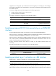
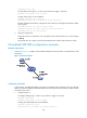
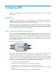
As shown in Figure 34, configure an ISDN PRI line between Router A and Router B for data transmission.
Figure 34 Network diagram
Configuration procedure
In this example, the ISDN PRI interfaces on Router A and Router B are operating as the user side (the
default). You must configure the ISDN PRI interfaces as the network side on the service provider switches
connected to the routers.
1. Configure Router A:
# Bundle timeslots into a PRI set on the CE1/PRI interface E1 2/3/0.
<RouterA> system-view
[RouterA] controller e1 2/3/0
[RouterA-E1 2/3/0] pri-set
[RouterA-E1 2/3/0] quit
# Configure dialer access group 1 to allow any IP packets to trigger a call setup.
[RouterA] dialer-group 1 rule ip permit
# Assign Serial 2/3/0:15 an IP address.
[RouterA] interface serial 2/3/0:15
[RouterA-Serial2/3/0:15] ip address 202.38.154.1 255.255.0.0
# Enable C-DDR on the interface, configure the route to Router B, and assign the interface to
dialer-group 1.
[RouterA-Serial2/3/0:15] dialer circular enable
[RouterA-Serial2/3/0:15] dialer route ip 202.38.154.2 8810154
[RouterA-Serial2/3/0:15] dialer-group 1
2. Configure Router B:
# Bundle timeslots into a PRI set on the CE1/PRI interface E1 2/3/0.
<RouterB> system-view
[RouterB] controller e1 2/3/0
[RouterB-E1 2/3/0] pri-set
ISDN network
CE1/PRI 2/3/0
202.38.154.1/16
8810152
CE1/PRI 2/3/0
202.38.154.2/16
8810154
Router A
Router B