
R0106-HP MSR Router Series Layer 2 - WAN Configuration Guide(V7)


111
Configuring ATM
ATM features are applicable to routers installed with ATM-OC3, ADSL2+, G.shdsl, or G.shdsl.Bis
interface cards.
Overview
Asynchronous Transfer Mode (ATM) is a technology based on packet transmission mode while
incorporating the high-speed of circuit transmission mode. Due to its flexibility and support for
multimedia services, ATM is regarded as a core broadband technology.
As defined by the ITU-T, data is encapsulated in cells in ATM. Each ATM cell is 53 bytes in length, of
which the first 5 bytes contain cell header information and the last 48 bytes contain payload. The major
function of the cell header is to identify virtual connection. In addition, it can be used to carry limited flow
control, congestion control, and error control information.
ATM connections and ATM switching
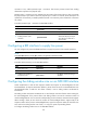
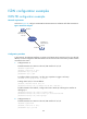
ATM is connection-oriented, and ATM connections are logical connections, or virtual circuits. In an ATM
network, you can create logical connections called virtual paths (VPs) and virtual circuits (VCs) on
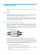
physical links. As shown in Figure 36, y
o
u can create multiple VPs on a physical link, and each VP can
be demultiplexed into multiple VCs. Cells from different users are transmitted over different VPs and VCs,
which are identified by virtual path identifier (VPI) and virtual channel identifier (VCI). ATM uses VPI/VCI
pairs to identify virtual circuits.
Figure 36 Physical link, VP, and VC
ATM interfaces support only manually created permanent virtual circuits (PVCs), not switched virtual
circuits (SVCs) created through the exchange of signals. A PVC is identified by a VPI/VCI pair.
In an ATM network, an ATM switch forwards ATM cells by looking up the switching entries and changing
the VPIs/VCIs. In PVC mode, the network administrator configures the switching entries and assigns
VPIs/VCIs. Users can use the assigned VPIs/VCIs to configure the PVCs. If the ATM interfaces of two ATM
devices are directly connected, they must be configured with the same VPIs/VCIs.
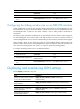
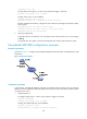
Figure 37 sh
o
ws a typical ATM switching process:
1. Router A forwards a cell through PVC 0/100 on interface ATM 2/4/1.
2. ATM switch B receives the cell through PVC 0/100 on interface ATM 2/4/1.
3. ATM switch B looks up its switching entries and forwards the cell through PVC 2/101 on interface
ATM 2/4/2.
4. Router C receives the cell through PVC 2/101 on interface ATM 2/4/1.