
R0106-HP MSR Router Series Layer 2 - WAN Configuration Guide(V7)

120
Ste
p
Command
Remarks
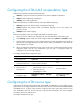
2. Create a VE subinterface
and enter VE subinterface
view.
interface virtual-ethernet
interface-number.subnumber
By default, no VE subinterface exists.
3. Configure the description
for the subinterface.
description text
By default, the description is in the format of
interface-name Interface.
4. Configure the MTU for the
subinterface.
mtu size
By default, the MTU for the subinterface is
1500 bytes.
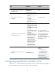
5. Configure the expected
bandwidth for the
subinterface.
bandwidth bandwidth-value
By default, the expected bandwidth (in kbps)
is the subinterface baud rate divided by
1000.
6. Restore the default settings
for the interface.
default
N/A
7. Shut down the
subinterface.
shutdown By default, the subinterface is up.
Configuring IPoA
To enable the upper layer protocols to find a remote device by its IP address, you must associate the local
PVC or PVC-group with the IP address of the remote device by mapping the IP address to the PVC or
PVC-group.
To configure an IP mapping, use one of the following methods:
• Static IP address mapping—Maps the IP address of the remote port to the PVC or PVC-group.
• Default mapping—If a packet cannot find the mapping for the next hop address, the packet is
transmitted through the PVC or PVC-group configured with the default mapping.
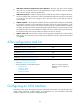
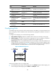
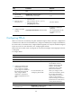
• InARP mapping—Uses Inverse Address Resolution Protocol (InARP) to resolve the IP address of the
remote port that is connected to the local PVC or PVC-group. You do not need to configure a static
IP address for the PVC or PVC-group. Figure 39 sho
w
s the InARP working process. The IP addresses
are the IP addresses of the ATM interfaces to which the PVC or PVC-group belongs.
Figure 39 InARP working process
Follow these guidelines when you configure IPoA:
• All encapsulation types support IPoA mapping, but only aal5snap supports InARP mapping. You
cannot configure InARP mapping when aal5mux or aal5nlpid is used.