
R0106-HP MSR Router Series Layer 2 - WAN Configuration Guide(V7)


123
Ste
p
Command
Remarks
6. Enter PVC view or PVC-group
view.
• Enter PVC view:
pvc { pvc-name [ vpi/vci ] |
vpi/vci }
• Enter PVC-group view:
pvc-group group-number
Use either method.
7. Configure a PPPoA mapping.
map ppp virtual-template
vt-number
By default, no mapping is
configured.
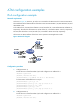
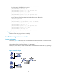
Configuring PPPoEoA
PPPoE uses the Client/Server model. It encapsulates PPP packets into Ethernet frames and provides
point-to-point connection on Ethernet. Perform this task to enable a PVC or PVC-group to carry PPPoE and
configure a PPPoE mapping for the PVC or PVC-group.
To configure PPPoEoA:
Ste
p
Command
Remarks
1. Enter system view.
system-view N/A
2. Create a VT interface.
interface virtual-template vt-number N/A
3. Configure PPP authentication
and IP address. For the PPP
server, configure an address
pool to assign an IP address
to the remote node. For the
PPP client, configure address
negotiation to accept the IP
address assigned by the
server end.
For more information, see "Configuring
PPP and MP."
Configure PPP authentication
and IP address on the VT
interface instead of an ATM
interface. The IP address
configuration does not take
effect on ATM interfaces.
When you configure a static
route for the VT interface,
specify the next hop instead of
the output interface. If you
have to specify an output
interface, make sure the
physical interface bound to the
VT is valid to ensure correct
packet transmission.
4. Return to system view.
quit N/A
5. Create a VE interface.
interface virtual-ethernet
interface-number
N/A
6. Configure PPPoE parameters
on the VE interface. Bind the
PPPoE server to a VT
interface, and bind the PPPoE
client to a Dialer interface for
dial-in access.
For more information, see "Configuring
PPPoE."
N/A
7. Return to system view.
quit N/A
8. Enter ATM interface view or
ATM subinterface view.
interface atm { interface-number |
interface-number.subnumber }
N/A