
R0106-HP MSR Router Series Layer 2 - WAN Configuration Guide(V7)


129
Configuration procedure
1. Configure Router C:
# Create a VE interface and configure an IP address for it.
<RouterC> system-view
[RouterC] interface virtual-ethernet 1
[RouterC-Virtual-Ethernet1] ip address 202.38.160.1 255.255.255.0
[RouterC-Virtual-Ethernet1] quit
# Create PVCs and enable them to carry IPoE.
[RouterC] interface atm 2/4/0.1
[RouterC-ATM2/4/0.1] pvc to_adsl_a 0/60
[RouterC-ATM2/4/0.1-pvc-to_adsl_a-0/60] map bridge virtual-ethernet 1
[RouterC-ATM2/4/0.1-pvc-to_adsl_a-0/60] quit
[RouterC-ATM2/4/0.1] pvc to_adsl_b 0/61
[RouterC-ATM2/4/0.1-pvc-to_adsl_b-0/61] map bridge virtual-ethernet 1
2. Configure ADSL Router A:
# Create a VE interface and configure an IP address for it.
<RouterA> system-view
[RouterA] interface virtual-ethernet 1
[RouterA-Virtual-Ethernet1] ip address 202.38.162.1 255.255.255.0
[RouterA-Virtual-Ethernet1] quit
# Create a PVC and enable it to carry IPoE.
[RouterA] interface atm 2/4/0.1
[RouterA-ATM2/4/0.1] pvc to_c 0/60
[RouterA-ATM2/4/0.1-pvc-to_c-0/60] map bridge virtual-ethernet 1
3. Configure ADSL Router B in the same way ADSL Router A is configured.
Verifying the configuration
Both ADSL Router A and ADSL Router B can ping Router C successfully.
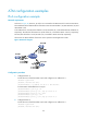
PPPoA configuration example
Network requirements
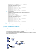
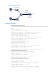
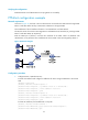
As shown in Figure 42, two hosts dial into the ATM network each through an ADSL router, and
communicate with Router C through DSLAM. This configuration example has the following requirements:
• Create VT for multiuser on Router C, and configure PPP mapping on VT.
• The VPI/VCI values of two PVCs connecting Router C and DSLAM are 0/60 and 0/61, pointing to
ADSL Router A and ADSL Router B, respectively.
• Both the WAN port of Router C and the DSL interfaces of the two ADSL routers use PPPoA. PPP
authentication is not performed. The IP addresses of the two ADSL routers are assigned by Router C.