
R0106-HP MSR Router Series Layer 2 - WAN Configuration Guide(V7)


131
Verifying the configuration
Both ADSL Router A and ADSL Router B can ping Router C successfully.
PPPoEoA configuration example
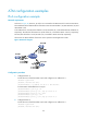
Network requirements
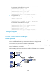
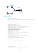
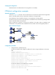
As shown in Figure 43, the hosts in the two Ethernets are connected to the ATM network through ADSL
Router A and ADSL Router B. They communicate with Router C through DSLAM.
The IP addresses of the VT interfaces of Router C are 202.38.160.1 and 202.38.161.1.
The VPI/VCI values of two PVCs connecting Router C and DSLAM are 0/60 and 0/61, pointing to ADSL
Router A and ADSL Router B, respectively.
Both the WAN port of Router C and the DSL interfaces of the ADSL routers use PPPoEoA. PPP
authentication is not performed. The IP addresses of the two ADSL routers are assigned by Router C.
Figure 43 Network diagram
Configuration procedure
1. Configure Router C (PPPoEoA server):
# Create VT interfaces and configure IP addresses for them. Assign IP addresses to the remote
ends.
<RouterC> system-view
[RouterC] interface virtual-template 10
[RouterC-Virtual-Template10] ip address 202.38.160.1 255.255.255.0
[RouterC-Virtual-Template10] remote address 202.38.162.1
[RouterC-Virtual-Template10] quit
[RouterC] interface virtual-template 11
[RouterC-Virtual-Template11] ip address 202.38.161.1 255.255.255.0
[RouterC-Virtual-Template11] remote address 202.38.162.2
[RouterC-Virtual-Template11] quit
# Create VE interfaces, and enable them to carry PPP.
[RouterC] interface virtual-ethernet 1
[RouterC-Virtual-Ethernet1] pppoe-server bind virtual-template 10
[RouterC-Virtual-Ethernet1] quit