
R0106-HP MSR Router Series Layer 2 - WAN Configuration Guide(V7)

133
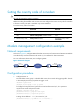
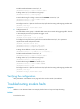
Configure Router A to distribute equal amount of traffic to Router B and Router C on the two PVCs and
observe the statistics of received/sent/dropped packets.
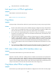
Figure 44 Network diagram
Configuration procedure
1. Configure Router A:
# Configure the ATM interface.
<RouterA> system-view
[RouterA] interface atm 2/4/0
[RouterA-Atm2/4/0] ip address 202.38.160.1 255.255.255.0
# Create two PVCs and assign them different transmission priorities.
[RouterA-ATM2/4/0] pvc 1 0/33
[RouterA-ATM2/4/0-pvc-1-0/33] map ip 202.38.160.2
[RouterA-ATM2/4/0-pvc-1-0/33] service ubr 100000
[RouterA-ATM2/4/0-pvc-1-0/33] transmit-priority 1
[RouterA-ATM2/4/0-pvc-1-0/33] quit
[RouterA-ATM2/4/0] pvc 2 0/32
[RouterA-ATM2/4/0-pvc-2-0/32] map ip 202.38.160.3
[RouterA-ATM2/4/0-pvc-2-0/32] service ubr 100000
[RouterA-ATM2/4/0-pvc-2-0/32] transmit-priority 3
After two equal amount of traffic exceeding the ATM bandwidth are sent to Router B and Router C,
you can use the display atm pvc-info command on Router B and Router C to view statistics of each
PVC. You can make several tests and observe the average statistics. The output shows that the PVC
with higher priority receives more packets than that with lower priority. The PVC with the higher
priority takes preference in getting bandwidth. Other PVCs, regardless of their priority values, are
treated equally in terms of bandwidth allocation.
Troubleshooting ATM
Link state error in IPoA application
Symptom
When IPoA is used, the link state is down.
Solution
• Verify that the optical fiber is connected correctly.
• Verify that the local IP address is configured.