
R0106-HP MSR Router Series Layer 2 - WAN Configuration Guide(V7)


177
[RouterC] line tty1
[RouterC-line-tty1] modem enable both
Verifying the configuration
# Verify that Router A can successfully ping Router B and Router C.
# Verify that Router B and Router C cannot ping each other.
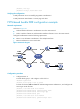
PSTN-based bundle DDR configuration example
Network requirements
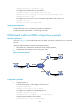
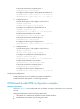
As shown in Figure 52:
• Dialer0 interfaces of Router A and Router B are in the same network.
• Dialer1 interface of Router A and the Dialer0 interface of Router C are in the same network.
Configure bundle DDR to meet the following requirements:
• Router A can call Router B and Router C from multiple interfaces.
• Router B and Router C cannot each other.
Figure 52 Network diagram
Configuration procedure
1. Configure Router A:
# Create dialer group 1 and configure a dial rule for it.
<RouterA> system-view
[RouterA] dialer-group 1 rule ip permit
# Create local users userb and userc for authenticating Router B and Router C, and configure the
service type as PPP for them.
[RouterA] local-user userb class network
[RouterA-luser-network-userb] password simple userb
[RouterA-luser-network-userb] service-type ppp
[RouterA-luser-network-userb] quit
[RouterA] local-user userc class network
[RouterA-luser-network-userc] password simple userc