
R0106-HP MSR Router Series Layer 2 - WAN Configuration Guide(V7)

23
[RouterB] interface serial 2/1/0
[RouterB-Serial2/1/0] link-protocol ppp
# Configure the PAP username and password sent from Router B to Router A when Router B is
authenticated by Router A using PAP.
[RouterB-Serial2/1/0] ppp pap local-user userb password simple passb
# Assign an IP address to Serial 2/1/0 of Router B.
[RouterB-Serial2/1/0] ip address 200.1.1.2 16
3. Verify the configuration:
Use the display interface serial command to display information about Serial 2/1/0 of Router B.
The physical layer status and link layer status of the interface are both up. The states of LCP and
IPCP are both Opened, indicating that PPP negotiation is successful. Router A and Router B can
ping each other.
[RouterB-Serial2/1/0] display interface serial 2/1/0
Serial2/1/0
Current state: UP
Line protocol state: UP
Description: Serial2/1/0 Interface
Bandwidth: 64kbps
Maximum Transmit Unit: 1500
Internet Address: 200.1.1.2/16 Primary
Link layer protocol: PPP
LCP: opened, IPCP: opened
...
[RouterB-Serial2/1/0] ping 200.1.1.1
5 packet(s) transmitted, 5 packet(s) received, 0.0% packet loss Ping 200.1.1.1
(200.1.1.1): 56 data bytes, press CTRL_C to break
56 bytes from 200.1.1.1: icmp_seq=0 ttl=128 time=3.197 ms
56 bytes from 200.1.1.1: icmp_seq=1 ttl=128 time=2.594 ms
56 bytes from 200.1.1.1: icmp_seq=2 ttl=128 time=2.739 ms
56 bytes from 200.1.1.1: icmp_seq=3 ttl=128 time=1.738 ms
56 bytes from 200.1.1.1: icmp_seq=4 ttl=128 time=1.744 ms
--- Ping statistics for 200.1.1.1 ---
5 packet(s) transmitted, 5 packet(s) received, 0.0% packet loss
round-trip min/avg/max/std-dev = 1.738/2.402/3.197/0.576 ms
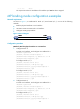
Two-way PAP authentication configuration example
Network requirements
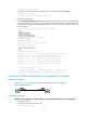
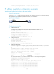
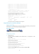
As shown in Figure 4, configure Router A and Router B to authenticate each other.
Figure 4 Network diagram