
R0106-HP MSR Router Series Layer 2 - WAN Configuration Guide(V7)


41
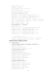
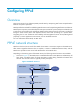
• As shown in Figure 11, a PPPoE session is established between each host (PPPoE client) and the
carrier router (PPPoE server). The service provider assigns an account to each host for billing and
control. The host must be installed with PPPoE client software.
Figure 11 Network structure 2
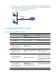
Configuring the PPPoE server
Configuring a PPPoE session
Ste
p
Command
Remarks
1. Enter system view.
system-view N/A
2. Create a VT interface and
enter VT interface view.
interface virtual-template number N/A
3. Set PPP parameters.
See "Configuring PPP."
If authentication is needed, use the
PPPoE server as the authenticator.
4. Return to system view.
quit N/A
5. Enter Layer 3 Ethernet
interface, Layer 3 virtual
Ethernet interface, or Layer 3
aggregate interface view.
interface interface-type
interface-number
N/A
6. Enable the PPPoE server on the
interface and bind this
interface to the specified VT
interface.
pppoe-server bind virtual-template
number
By default, the PPPoE server is
disabled on the interface.
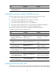
7. (Optional.) Configure an
access controller (AC) name
for the PPPoE server.
pppoe-server tag ac-name name
By default, the AC name for the
PPPoE server is the device name.
PPPoE clients can choose a PPPoE
server according to the AC name.
The PPPoE client on HP devices do
not support this feature.
8. (Optional.) Enable the PPPoE
server to support the
ppp-max-payload tag and
specify a range for the PPP
maximum payload.
pppoe-server tag
ppp-max-payload [ minimum
minvalue maximum maxvalue ]
By default, The PPPoE server does
not support the ppp-max-payload
tag.
9. Return to system view.
quit N/A
Internet
PPPoE server
Host A
Host B
Router
PPPoE client
PPPoE client