
R0106-HP MSR Router Series Layer 2 - WAN Configuration Guide(V7)


61
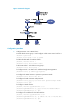
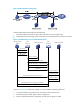
As shown in Figure 23, the workflow for establishing a client-initiated tunnel is similar to that for
establishing a NAS-initiated tunnel. (Details not shown.)
Figure 23 Establishment process for client-initiated tunnels
LAC-auto-initiated tunneling mode
In NAS-initiated mode, a remote system must successfully dial in to the LAC through PPPoE or ISDN.
In LAC-auto-initiated mode, you can use the l2tp-auto-client command on the LAC to trigger the LAC to
initiate a tunneling request to the LNS. When a remote system accesses the internal network, the LAC
forwards data through the L2TP tunnel.
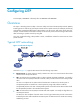
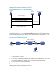
Figure 24 LAC-auto-initiated tunneling mode
An LAC-auto-initiated tunnel has the following characteristics:
• The connection between a remote system and the LAC is not confined to a dial-up connection and
can be any IP-based connection.
• An L2TP session is established immediately after an L2TP tunnel is established. Then, the LAC and
LNS, acting as the PPPoE client and PPPoE server, respectively, perform PPP negotiation.
• An L2TP tunnel can carry only one L2TP session.
• The LNS assigns a private IP address to the LAC instead of to the remote system.
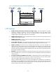
As shown in Figure 25, the w
o
rkflow for establishing an LAC-auto-initiated tunnel is similar to that for
establishing a NAS-initiated tunnel. (Details not shown.)
(1) Tunnel setup request
(2) CHAP authentication (challenge/response)
(3) Setup a session
(4) LCP negotiation and user authentication
(5) Access request
(6) Acesss accept
(7) Authentication passes, and assign an IP address
LNS
Device A
RADIUS server
LAC client
Host A
(8) Access the private network
LAN
Internet
Remote system
Host A
Private
network
L2TP tunnel
LAC auto initiated
LAC
Device A
LNS
Device B
RADIUS server