
R0106-HP MSR Router Series Layer 3 - IP Routing Configuration Guide(V7)


122
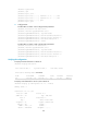
# Display OSPF neighbors on Router B to verify the neighbor relationship between Router B and
Router S.
<RouterB> display ospf peer
OSPF Process 1 with Router ID 4.4.4.1
Neighbor Brief Information
Area: 0.0.0.0
Router ID Address Pri Dead-Time State Interface
3.3.3.1 14.14.14.2 1 39 Full/BDR GE2/1/1
# Display OSPF routes on Router B to verify if there are routes from Router B to the loopback
interface on Router A.
<RouterB> display ospf routing
OSPF Process 1 with Router ID 4.4.4.1
Routing Tables
Routing for Network
Destination Cost Type NextHop AdvRouter Area
44.44.44.44/32 0 Stub 44.44.44.44 4.4.4.1 0.0.0.0
14.14.14.0/24 1 Transit 14.14.14.1 4.4.4.1 0.0.0.0
22.22.22.22/32 2 Stub 14.14.14.2 2.2.2.1 0.0.0.0
12.12.12.0/24 2 Transit 14.14.14.2 2.2.2.1 0.0.0.0
Total Nets: 4
Intra Area: 4 Inter Area: 0 ASE: 0 NSSA: 0
The output shows that when an active/standby switchover occurs on Router S, the neighbor
relationships and routing information on Router A and Router B have not changed, and the traffic
from Router A to Router B has not been impacted.
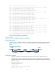
BFD for OSPF configuration example
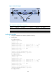
Network requirements
As shown in Figure 31, run OSPF on Router A, Router B, and Router C so that they can reach each other
at the network layer.
• When the link over which Router A and Router B communicate through a Layer 2 switch fails, BFD
can quickly detect the failure and notify OSPF of the failure.
• Router A and Router B then communicate through Router C.