
R0106-HP MSR Router Series Layer 3 - IP Routing Configuration Guide(V7)


123
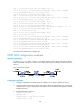
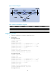
Figure 31 Network diagram
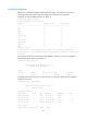
Table 7 Interface and IP address assignment
Device Interface IP address
Device
Interface
IP address
Router A GE2/1/1 192.168.0.102/24
Router B
GE2/1/2 13.1.1.1/24
Router A GE2/1/2 10.1.1.102/24
Router C
GE2/1/1 10.1.1.100/24
Router B GE2/1/1 192.168.0.100/24
Router C GE2/1/2 13.1.1.2/24
Configuration procedure
1. Configure IP addresses for interfaces. (Details not shown.)
2. Enable OSPF:
# Configure Router A.
<RouterA> system-view
[RouterA] ospf
[RouterA-ospf-1] area 0
[RouterA-ospf-1-area-0.0.0.0] network 192.168.0.0 0.0.0.255
[RouterA-ospf-1-area-0.0.0.0] network 10.1.1.0 0.0.0.255
[RouterA-ospf-1-area-0.0.0.0] network 121.1.1.0 0.0.0.255
[RouterA-ospf-1-area-0.0.0.0] quit
[RouterA-ospf-1] quit
[RouterA] interface gigabitethernet 2/1/2
[RouterA-GigabitEthernet2/1/2] ospf cost 2
# Configure Router B.
<RouterB> system-view
[RouterB] ospf
[RouterB-ospf-1] area 0
[RouterB-ospf-1-area-0.0.0.0] network 192.168.0.0 0.0.0.255
[RouterB-ospf-1-area-0.0.0.0] network 13.1.1.0 0.0.0.255
[RouterB-ospf-1-area-0.0.0.0] network 120.1.1.0 0.0.0.255
[RouterB-ospf-1-area-0.0.0.0] quit
[RouterB-ospf-1] quit
[RouterB] interface gigabitethernet 2/1/2
[RouterB-GigabitEthernet2/1/2] ospf cost 2
# Configure Router C.