
R0106-HP MSR Router Series Layer 3 - IP Routing Configuration Guide(V7)


125
Flags: 0x1008c OrigNextHop: 192.168.0.100
Label: NULL RealNextHop: 192.168.0.100
BkLabel: NULL BkNextHop: N/A
Tunnel ID: Invalid Interface: GigabitEthernet2/1/1
BkTunnel ID: Invalid BkInterface: N/A
The output shows that Router A communicates with Router B through GigabitEthernet 2/1/1. Then the
link over GigabitEthernet 2/1/1 fails.
# Display routes destined for 120.1.1.0/24 on Router A.
<RouterA> display ip routing-table 120.1.1.0 verbose
Summary Count : 1
Destination: 120.1.1.0/24
Protocol: OSPF Process ID: 1
SubProtID: 0x1 Age: 04h20m37s
Cost: 4 Preference: 10
Tag: 0 State: Active Adv
OrigTblID: 0x0 OrigVrf: default-vrf
TableID: 0x2 OrigAs: 0
NBRID: 0x26000002 LastAs: 0
AttrID: 0xffffffff Neighbor: 0.0.0.0
Flags: 0x1008c OrigNextHop: 10.1.1.100
Label: NULL RealNextHop: 10.1.1.100
BkLabel: NULL BkNextHop: N/A
Tunnel ID: Invalid Interface: GigabitEthernet2/1/2
BkTunnel ID: Invalid BkInterface: N/A
The output shows that Router A communicates with Router B through GigabitEthernet 2/1/2.
OSPF FRR configuration example
Network requirements
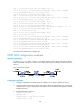
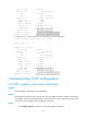
As shown in Figure 32, Router S, Router A, and Router D reside in the same OSPF domain. Configure
OSPF FRR so that when Link A fails, traffic is immediately switched to Link B.
Figure 32 Network diagram
Configuration procedure
1. Configure IP addresses and subnet masks for interfaces on the routers. (Details not shown.)