
R0106-HP MSR Router Series Layer 3 - IP Routing Configuration Guide(V7)


168
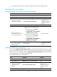
Task Command
Display IS-IS IPv4 topology information.
display isis spf-tree [ ipv4 [ topology topo-name ] ] [ [ level-1 |
level-2 ] | verbose ] * [ process-id ]
Display IS-IS statistics.
display isis statistics [ ipv4 [ topology topo-name ] ] [ level-1 |
level-1-2 | level-2 ] [ process-id ]
Display OSI connection information
(MSR2000/MSR3000).
display osi
Display OSI connection information
(MSR4000).
display osi [ slot slot-number ]
Display OSI connection statistics
(MSR2000/MSR3000).
display osi statistics
Display OSI connection statistics
(MSR4000).
display osi statistics [ slot slot-number ]
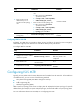
Clear IS-IS process data structure
information.
reset isis all [ process-id ] [ graceful-restart ]
Clear IS-IS GR log information
(MSR2000/MSR3000).
reset isis graceful-restart event-log
Clear IS-IS GR log information
(MSR4000).
reset isis graceful-restart event-log slot slot-number
Clear IS-IS NSR log information
(MSR2000/MSR3000).
reset isis non-stop-routing event-log slot slot-number
Clear IS-IS NSR log information
(MSR4000).
reset isis non-stop-routing event-log slot slot-number
Clear the data structure information of an
IS-IS neighbor.
reset isis peer system-id [ process-id ]
Clear OSI connection statistics. reset osi statistics
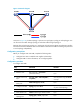
IS-IS configuration examples
Basic IS-IS configuration example
Network requirements
As shown in Figure 42, Router A, Router B, Router C, and Router D reside in an AS.
Router A and Router B are Level-1 routers, Router D is a Level-2 router, and Router C is a Level-1-2 router
connecting two areas. Router A, Router B, and Router C are in area 10, and Router D is in area 20.