
R0106-HP MSR Router Series Layer 3 - IP Routing Configuration Guide(V7)


188
The output shows that the neighbor information and routing information on Router A and Router B have
not changed during the active/standby switchover on Router S. The neighbors are unaware of the
switchover.
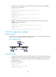
BFD for IS-IS configuration example
Network requirements
• As shown in Figure 48, run IS-IS on Router A, Router B and Router C so that they can reach each
other at the network layer.
• After the link over which Router A and Router B communicate through the Layer 2 switch fails, BFD
can quickly detect the failure and notify IS-IS of the failure. Router A and Router B then communicate
through Router C.
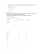
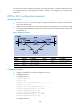
Figure 48 Network diagram
Device Interface IP address
Device
Interface
IP address
Router A GE2/1/1 192.168.0.102/24
Router B GE2/1/1 192.168.0.100/24
GE2/1
/
2 10.1.1.102/24
GE2/1
/
2 13.1.1.1/24
Router C GE2/1
/
1 10.1.1.100/24
GE2/1/2 13.1.1.2/24
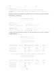
Configuration procedure
1. Configure IP addresses for interfaces. (Details not shown.)
2. Configure basic IS-IS:
# Configure Router A.
<RouterA> system-view
[RouterA] isis
[RouterA-isis-1] network-entity 10.0000.0000.0001.00
[RouterA-isis-1] quit
[RouterA] interface gigabitethernet 2/1/1
[RouterA-GigabitEthernet2/1/1] isis enable
[RouterA-GigabitEthernet2/1/1] quit
[RouterA] interface gigabitethernet 2/1/2
[RouterA-GigabitEthernet2/1/2] isis enable
[RouterA-GigabitEthernet2/1/2] quit
# Configure Router B.