
R0106-HP MSR Router Series Layer 3 - IP Routing Configuration Guide(V7)


17
Ping statistics for 1.1.2.2:
Packets: Sent = 4, Received = 4, Lost = 0 (0% loss),
Approximate round trip times in milli-seconds:
Minimum = 1ms, Maximum = 1ms, Average = 1ms
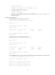
# Use the tracert command on Host B to test the reachability of Host A.
C:\Documents and Settings\Administrator>tracert 1.1.2.2
Tracing route to 1.1.2.2 over a maximum of 30 hops
1 <1 ms <1 ms <1 ms 1.1.6.1
2 <1 ms <1 ms <1 ms 1.1.4.1
3 1 ms <1 ms <1 ms 1.1.2.2
Trace complete.
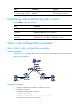
BFD for static routes configuration example (direct next hop)
Network requirements
As shown in Figure 3:
• Configure a static route to subnet 120.1.1.0/24 on Router A.
• Configure a static route to subnet 121.1.1.0/24 on Router B.
• Enable BFD for both routes.
• Configure a static route to subnet 120.1.1.0/24 and a static route to subnet 121.1.1.0/24 on Router
C.
When the link between Router A and Router B through the Layer 2 switch fails, BFD can detect the failure
immediately and inform Router A and Router B to communicate through Router C.
Figure 3 Network diagram
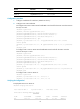
Table 4 Interface and IP address assignment
Device Interface
IP
address
Router A GigabitEthernet 2/1/1 12.1.1.1/24
Router A GigabitEthernet 2/1/2 10.1.1.102/24
Router B GigabitEthernet 2/1/1 12.1.1.2/24
Router B GigabitEthernet 2/1/2 13.1.1.1/24