
R0106-HP MSR Router Series Layer 3 - IP Routing Configuration Guide(V7)


293
IPv4 BGP configuration examples
Basic BGP configuration example
Network requirements
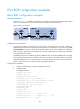
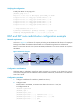
As shown in Figure 65, run EBGP between Router A and Router B, and run IBGP between Router B and
Router C so that Router C can access the net w o rk 8 .1.1.0 / 24 c o n n e c t e d t o R o u t e r A .
Figure 65 Network diagram
Configuration considerations
To prevent route flapping caused by port state changes, this example uses loopback interfaces to
establish IBGP connections. Because loopback interfaces are virtual interfaces, you need to use the peer
connect-interface command to specify the loopback interface as the source interface for establishing
BGP connections. Enable OSPF in AS 65009 to make sure that Router B can communicate with Router
C through loopback interfaces.
The EBGP peers, Router A and Router B (usually in different ISPs), are located in different ASs. Typically,
their loopback interfaces are not reachable to each other, so directly connected interfaces are used for
establishing EBGP sessions. To enable Router C to access the network 8.1.1.0/24 connected directly to
R o u t e r A , i n j e c t n e t wo rk 8 .1.1.0 / 24 t o the BGP routing table of Router A.
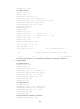
Configuration procedure
1. Configure IP addresses for interfaces. (Details not shown.)
2. Configure IBGP:
# Configure Router B.
<RouterB> system-view
[RouterB] bgp 65009
[RouterB-bgp] router-id 2.2.2.2
[RouterB-bgp] peer 3.3.3.3 as-number 65009
[RouterB-bgp] peer 3.3.3.3 connect-interface loopback 0
[RouterB-bgp] address-family ipv4 unicast
[RouterB-bgp-ipv4] peer 3.3.3.3 enable
[RouterB-bgp-ipv4] quit
[RouterB-bgp] quit
[RouterB] ospf 1
[RouterB-ospf-1] area 0
[RouterB-ospf-1-area-0.0.0.0] network 2.2.2.2 0.0.0.0
[RouterB-ospf-1-area-0.0.0.0] network 9.1.1.0 0.0.0.255
[RouterB-ospf-1-area-0.0.0.0] quit